Phone number:0086-0577-61731588
Fax:0086-0577-61731588
Cell phone:+86 18072180777
Wechat:+86 18072180777
Website:www.china-relay.com
Zhiguang Industrial Zone, Liu Town, Yueqing, Zhejiang, China
Delay range: 0.125 ~ 1.25s, 0.5 ~ 5s, 1 ~ 10s, 2 ~ 20s
Setting voltage: DC: 100, 110, 127, 220V
Communication: 24, 48, 110, 220V, 380V
Operating voltage: current :≤85% DC :≤ 70%
Return voltage ≥5%
Power consumption: 15 ~ 25W
Contact capacity: dc sensitivity 100W
Long-term allowable current 5A
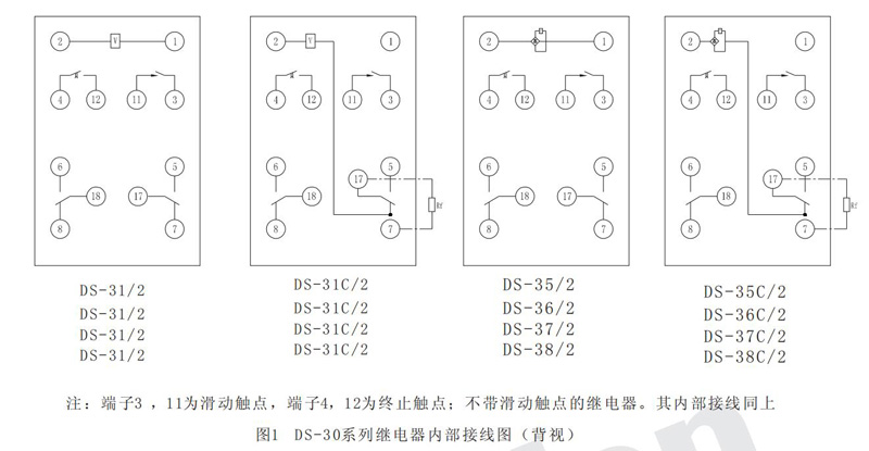
Contact form: one pair of transient conversions, one pair of slides, one pair of stops
Opening size: 107.5×62.5mm
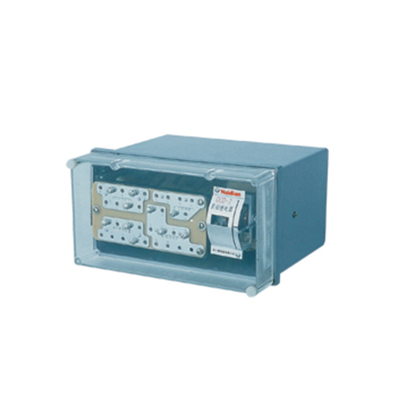
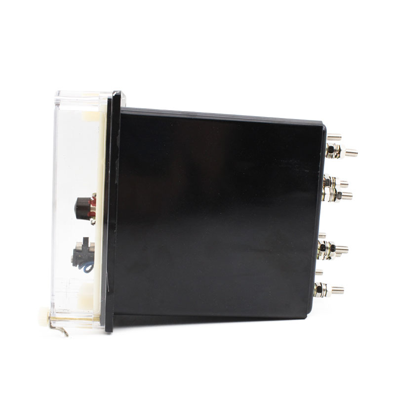
Installation mode: A11K, H, Q shell
Note: THE DC band "C" is for long-term operation
Usage
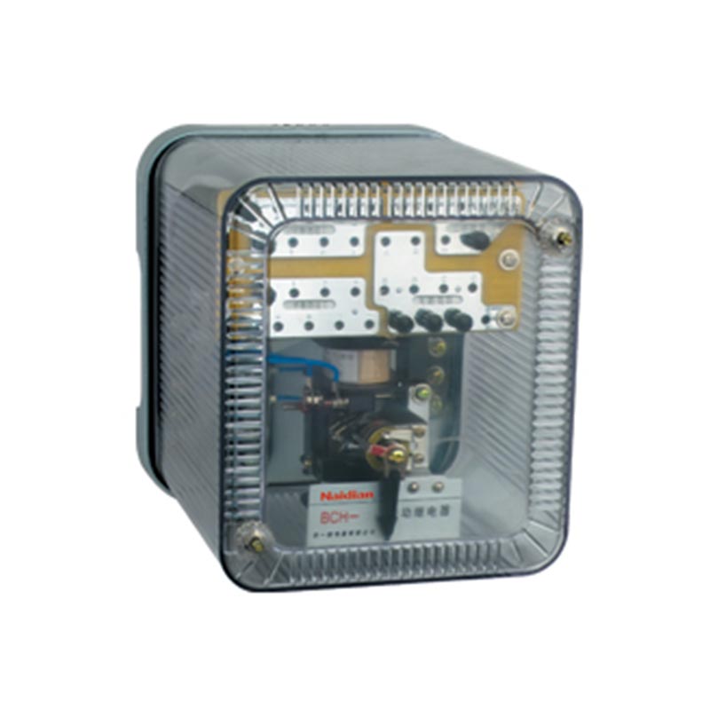
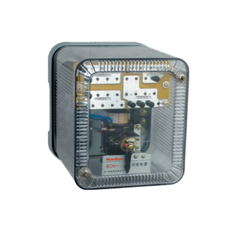
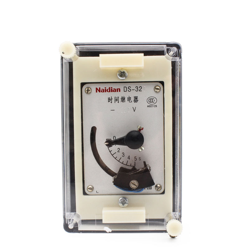
Ds-30 series time relays (hereinafter referred to as relays) are used as auxiliary components in various protection and automatic devices to enable controlled elements to reach the required delay time and realize the selective coordination between primary protection and backup protection in the protection device.
Structure and principl
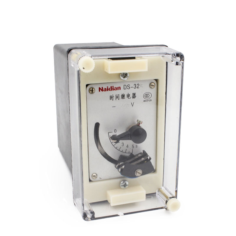
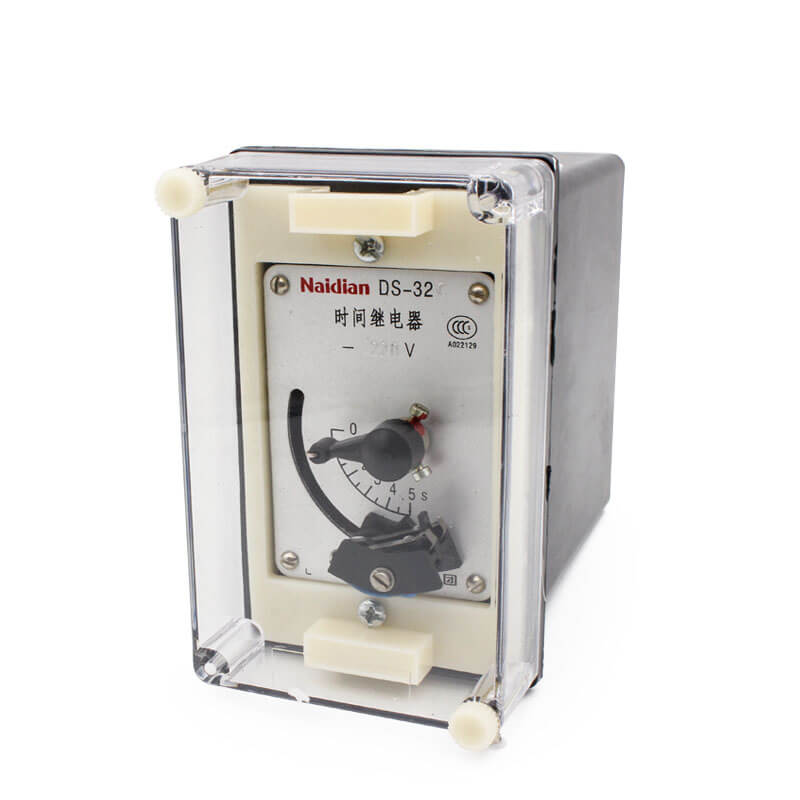
1. This relay is an electromagnet that drives a clock delay mechanism. The electromagnet can be powered by DC or AC power.There are two sets of instantaneous conversion contacts in each relay. One set of delay main contact (termination contact) can be installed according to different specifications. The delay setting value can be equal to or less than the delay setting value of the delay main contact.Relay installation and connection modes are different. The same movement can have two structural forms, namely, A11K is embedded installation.A11H is for wiring after convex installation, as shown in the attached figure 3 in this manual. The cover of the relay can be equipped with a trailing needle to indicate the operation of the relay. (The type with X in the specification table is the specification with a trailing needle) In order to facilitate maintenance, there is a plug-in inside the relay, and the relay part can be extracted after the cover is removed.
Relay no gesture, snap switch contact close contact closure, delay off contact, pulling the needle refers to zero, when the magnet power supply, electromagnet suction, instantaneous contact with instantaneous switch, clockwork began to turn, delay action contact to close direction, driven in pulling the needle at the same time, according to the setting of delay contact sliding contact and main contact successively connected, after connecting a main contact due to the rotation stop limit agencies, institutions stops, the relay will be a long stay in the main contact closure, that when the power disconnect each contact instantaneous return to original state, after pulling the needle to stay in there,The indicated value shall comply with the set values for the main contact, (in fact drag pointer value should be a little more than the set values for the main contact, because contact the slide after connect can still be a distance, additional power when the power supply when the delay unfinished, is pulling the needle indicated time fully equal to the set values for the moving contact, thus pulling the needle can indicate the relay reset time, facilitate analysis problem) pulling the needle can be on the outside of the relay device reset, the knob on the lid: clockwise direction, the first pulling the needle moving contact and stop, continue to turn the knob, the zero alignment to pull the needle on a disc.
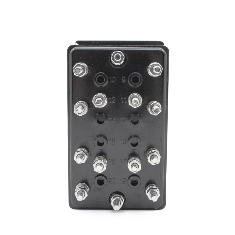
2. See Figure 1 for the internal wiring diagram of the relay.
3. Dc relay operating voltage shall not be greater than 70% rated voltage, AC relay operating voltage shall not be greater than 85% rated voltage, return voltage shall not be less than 5% rated voltage.
4. Delay error of relay :(refers to the difference between the maximum and minimum values in 10 actions at 20+5℃)
DS, DS - 31-31 c, 35, DS - DS - 35 c is 0.06 s.
DS, DS - 32-32 c, DS - 36, DS - 36 c 0.125 s.
Ds-33, DS-33C,DS-37, and DS-37 are 0.25s.
DS, DS - 34-34 c, DS - 38, DS - 38 c 0.5 s.
5. Power consumption of relay coils at rated voltage
For SHORT dc work: DS-31,DS-32,DS-33,DS-34 not greater than 25W.
For dc long working hours: DS-31C,DS-32C,DS-33C,DS-34C not greater than 15W.
"Ds-35,DS-36,DS-37, AND DS-38 are not greater than 20VA for short exchange work.
"Ds-35c,DS-36C,DS-37C,DS-38C are not greater than 20VA for short exchange work.
6. Thermal stability
For short time ac/DC operation, the coil can withstand 110% rated voltage for two minutes and the temperature rise is not greater than 65℃.
For long time dc ac operation, the coil (via additional resistance) can withstand 110% rated voltage for a long time, with temperature rise not greater than 65℃.
7. Each contact of the relay is disconnected and the inductive load is 50W.(U is not greater than 220V,I is not greater than 1A, and T is less than 5ms).
8. The relay contact can close current 5A for a long time.
9. The insulation strength of the live part of the relay to the magnetic conducting body can withstand AC 50Hz and 2KV for 1min without breakdown.
10. The relay can work 5000 times without mechanical damage.
11. Relay operating temperature range: -20-+40℃.
Use and maintenance
1. The user should pay attention to the rated working mode of the relay. If the relay operated for a short time is used in the long live situation of the coil circuit, the coil of the relay will overheat and be damaged.The long-term working relay has external resistance and should be connected according to the Rf position in the attached drawing when in use.
2. The relay shall be mounted on a plate perpendicular to the horizontal plane and shall be energized before being put into operation.In order not to be able to return to the original position due to the action of each part.The error that causes the delay.
3. When the relay is in maintenance, the other parts of its clock and watch mechanism shall be cleaned with aviation gasoline, and then the active 4# aviation instrument oil shall be applied at the points of each movable part (sliding contact part), and low temperature grease shall be applied between the CAM directly driven by the electromagnetic and the sector tooth plate.The electromagnetic parts, moving core and coil tube should be cleaned.
Technical data
1. Relay type description:
Example: 31 c/DS - 2 xa11k
Where: DS stands for electromagnetic time relay.
31-38 is the design serial number, and the second number is used to represent both the delay range and the type of power supply (1-4 is the four delay range and dc power supply; 5-8 is the same delay range as 1-4, but ac power supply).
PI over 2 indicates a sliding delay contact.
/X means I have a drag pin.(See Table 1)
11K represents the embedded installation and the back wiring
The above example is embedded time relay with sliding delay contact and towing pin, with post-connection delay of 0.125-1.25s for long-term operation (the model cannot represent the voltage specification, so the rated voltage should be indicated when ordering).
2. Coil resistance value (see Table 2)
3. Weight: 1Kg
Appearance and hole size
The relay adopts A11,A11H and A11Q housing, and the outline and installation hole size are shown in Figure 3 attached on page 288 of this manual.
Table 1
|
Model |
Shell structure |
Power Supply |
Delay Time(S) |
Working Method |
Sliding contact |
Drag the needle |
Rated Voltage (V) |
Notes |
|
DS- 31 - |
A 11K A 11H A 11Q |
DC |
0.0125-1.25 |
Short term |
|
|
220,110,48,24 |
|
|
DS- 31 / 2 - |
0.0125-1.25 |
+ |
|
220,110,48,24 |
|
|||
|
DS- 31 / X- |
0.0125-1.25 |
|
+ |
220,110,48,24 |
|
|||
|
DS- 31 / 2 X- |
0.0125-1.25 |
+ |
+ |
220,110,48,24 |
|
|||
|
DS- 32 - |
0.5-5 |
|
|
220,110,48,24 |
|
|||
|
DS- 32 / 2 - |
0.5-5 |
+ |
+ |
220,110,48,24 |
|
|||
|
DS- 32 / X- |
0.5-5 |
|
+ |
220,110,48,24 |
|
|||
|
DS- 32 / 2 X- |
0.5-5 |
+ |
+ |
220,110,48,24 |
|
|||
|
DS- 33 - |
1-10 |
|
|
220,110,48,24 |
|
|||
|
DS- 33 / 2 - |
1-10 |
+ |
|
220,110,48,24 |
|
|||
|
DS- 33 / X- |
1-10 |
|
+ |
220,110,48,24 |
|
|||
|
DS- 33 / 2 X- |
1-10 |
+ |
+ |
220,110,48,24 |
|
|||
|
DS- 34 - |
2-20 |
|
|
220,110,48,24 |
|
|||
|
DS- 34 / 2 - |
2-20 |
+ |
|
220,110,48,24 |
|
|||
|
DS- 34 / X- |
2-20 |
|
+ |
220,110,48,24 |
|
|||
|
DS- 34 / 2 X- |
2-20 |
+ |
+ |
220,110,48,24 |
|
|||
|
DS- 31 C- |
0.0125-1.25 |
Long term |
|
|
220,110,48,24 |
With resistance |
||
|
DS- 31 C/ 2 - |
0.0125-1.25 |
+ |
|
220,110,48,24 |
With resistance |
|||
|
DS- 31 C/ X- |
0.0125-1.25 |
|
+ |
220,110,48,24 |
With resistance |
|||
|
DS- 31 C/ 2 X- |
0.0125-1.25 |
+ |
+ |
220,110,48,24 |
With resistance |
|||
|
DS- 32 C- |
0.5-5 |
|
|
220,110,48,24 |
With resistance |
|||
|
DS- 32 C/ 2 - |
0.5-5 |
+ |
|
220,110,48,24 |
With resistance |
|||
|
DS- 32 C/ X- |
0.5-5 |
|
+ |
220,110,48,24 |
With resistance |
|||
|
DS- 32 C/ 2 X- |
0.5-5 |
+ |
+ |
220,110,48,24 |
With resistance |
|||
|
DS- 33 C- |
1-10 |
|
|
220,110,48,24 |
With resistance |
|||
|
DS- 33 C/ 2 - |
1-10 |
+ |
|
220,110,48,24 |
With resistance |
|||
|
DS- 33 C/ X- |
1-10 |
|
+ |
220,110,48,24 |
With resistance |
|||
|
DS- 33 C/ 2 X- |
1-10 |
+ |
+ |
220,110,48,24 |
With resistance |
|||
|
DS- 34 C- |
2-20 |
|
|
220,110,48,24 |
With resistance |
|||
|
DS- 34 C/ 2 - |
2-20 |
+ |
|
220,110,48,24 |
With resistance |
|||
|
DS- 34 C/ X- |
2-20 |
|
+ |
220,110,48,24 |
With resistance |
|||
|
DS- 34 C/ 2 X- |
2-20 |
+ |
+ |
220,110,48,24 |
With resistance |
|||
|
DS- 35 - |
AC |
0.0125-1.25 |
Short Term |
|
+ |
220,127,110,100 |
|
|
|
DS- 35 / 2 - |
0.0125-1.25 |
+ |
|
220,127,110,100 |
|
|||
|
DS- 36 - |
5.5-5 |
|
|
220,127,110,100 |
|
Continue table
|
Model |
Shell structure |
Power Supply |
Delay time(s) |
Work Method |
Sliding contact |
Drag the needle |
Rated Volatge(V) |
Note |
|
DS- 31 C- |
A11Q |
|
0.0125-1.25 |
Long Term |
|
|
220,110,48,24 |
With resistance |
|
DS- 31 C/ 2 - |
|
|
0.0125-1.25 |
|
+ |
|
220,110,48,24 |
With resistance |
|
DS- 31 C/ X- |
|
|
0.0125-1.25 |
|
|
+ |
220,110,48,24 |
With resistance |
|
DS- 31 C/ 2 X- |
|
|
0.0125-1.25 |
|
+ |
+ |
220,110,48,24 |
With resistance |
|
DS- 32 C- |
|
|
0.5-5 |
|
|
|
220,110,48,24 |
With resistance |
|
DS- 32 C/ 2 - |
|
|
0.5-5 |
|
+ |
|
220,110,48,24 |
With resistance |
|
DS- 32 C/ X- |
|
|
0.5-5 |
|
|
+ |
220,110,48,24 |
With resistance |
|
DS- 32 C/ 2 X- |
|
|
0.5-5 |
|
+ |
+ |
220,110,48,24 |
With resistance |
|
DS- 33 C- |
|
|
1-10 |
|
|
|
220,110,48,24 |
With resistance |
|
DS- 33 C/ 2 - |
|
|
1-10 |
|
+ |
|
220,110,48,24 |
With resistance |
|
DS- 33 C/ X- |
|
|
1-10 |
|
|
+ |
220,110,48,24 |
With resistance |
|
DS- 33 C/ 2 X- |
|
|
1-10 |
|
+ |
+ |
220,110,48,24 |
With resistance |
|
DS- 34 C- |
|
|
2-20 |
|
|
|
220,110,48,24 |
With resistance |
|
DS- 34 C/ 2 - |
|
|
2-20 |
|
+ |
|
220,110,48,24 |
With resistance |
|
DS- 34 C/ X- |
|
|
2-20 |
|
|
+ |
220,110,48,24 |
With resistance |
|
DS- 34 C/ 2 X- |
|
|
2-20 |
|
+ |
+ |
220,110,48,24 |
With resistance |
Table 2
|
Model |
Rated voltage( V) |
The coil resistance( Ω) |
|
|
DS- 31 |
- 220 |
1900 |
|
|
DS- 32 |
- 110 |
580 |
|
|
DS- 33 |
- 48 |
110 |
|
|
DS- 34 |
- 24 |
26 |
|
|
DS- 31 C |
- 220 |
780 |
2700 |
|
DS- 32 C |
- 110 |
165 |
680 |
|
DS- 33 C |
- 48 |
35 |
130 |
|
DS- 34 C |
- 24 |
8 . 5 |
33 |
|
DS- 35 |
- 220 |
1900 |
|
|
DS- 36 |
- 127 |
850 |
|
|
DS- 37 |
- 110 |
580 |
|
|
DS- 38 |
- 100 |
550 |
|
|
DS- 35 C |
- 220 |
780 |
2700 |
|
DS- 36 C |
- 127 |
190 |
680 |
|
DS- 37 C |
- 110 |
165 |
680 |
|
DS- 38 C |
- 100 |
150 |
510 |
Message feedback
News Center
Naidian Group is an electronic timer manufacturer and digital timer supplier, providing high-power relays, electronic time relays, digital timer relays, DC to AC solid state relays, and digital display timer relay knowledge popularization.
On February 26, the production of NPOWER Group resumed. The director and manager of our company personall...
A digital display time relay — ±0.1% accuracy, no drift. LED display, 0.01s–99h range. Reliable timing fo...
A digital time relay provides precise timing for control circuits — delay, interval, off-delay, or cyclic...
A solid state relay lasts longer with no moving parts to wear. Lifespan depends on thermal management — p...

GET A QUOTE