Phone number:0086-0577-61731588
Fax:0086-0577-61731588
Cell phone:+86 18072180777
Wechat:+86 18072180777
Website:www.china-relay.com
Zhiguang Industrial Zone, Liu Town, Yueqing, Zhejiang, China
Rated current :5A(50Hz)
Ampere turns :60±4
Setting range:
Two-winding generator 1.55 ~ 12A
Three-winding transformer 3 ~ 12A
Reliability coefficient :5 times ≤1.35 times A2 ≤ 1.2a
Power consumption :≤16VA
Contact form: move and close
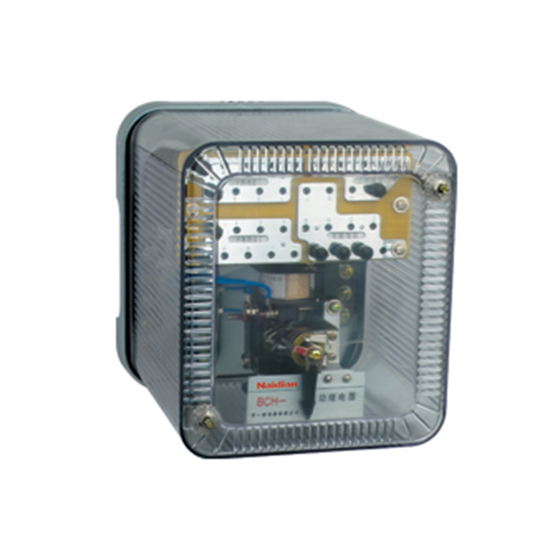
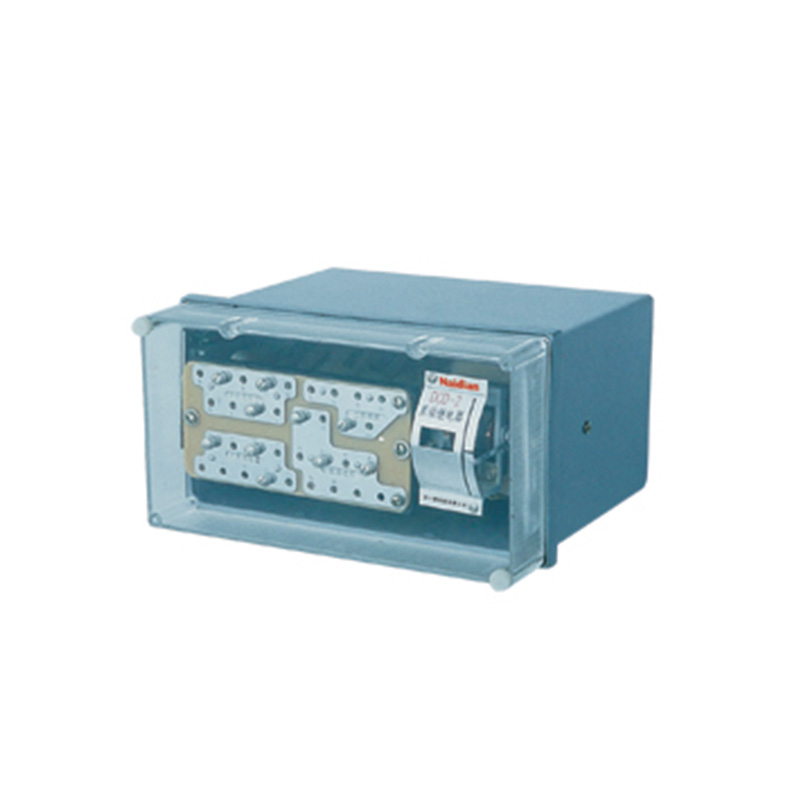
Installation method: HK-7 shell is adopted
Usage
The relay has a brake winding which can protect the power transformer with single-phase differential with two winding and three winding.
Summary of structure
The relay consists of a DL-11 electromagnetic current relay (the actuator) and an intermediate fast saturated converter (hereinafter referred to as the converter).
The relay has braking windings, which constitute some of the main technical properties of the differential relay, such as braking characteristics, the ability to avoid magnetizing insurge current characteristics, and the ability of the auto-transformer to eliminate the unbalanced current effect.
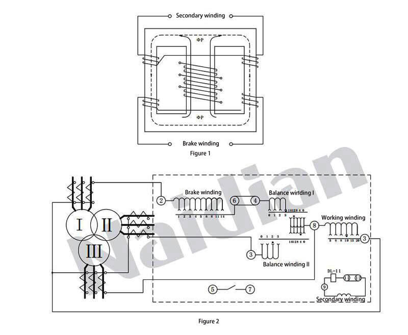
Converter magnetizer is a three cylindrical iron core, with several groups of "mountain" form magnetic slice of piled up and work on the stele of magnetizer rotation and balanced windings I, II, braking and secondary windings are divided into two parts, respectively on the two side column magnetic conductor, the connection makes the brake winding and secondary winding and balance winding I, II, and without mutual induction between the induction voltage in the secondary winding is produced by magnetization of the work winding, in order to change the magnetizer is the degree of saturation of the converter, braking winding circle number can be changed.
The converter can prevent both magnetizing inrush current and relay misoperation when the power transformer crosses the fault.The converter and actuator are placed in a housing, and the connection can be made before and after the board when the relay is installed.The transformer wiring diagram is shown in Figure 1, and the relay outer pair wiring is shown in Figure 2 when protecting the three-winding power transformer.
A converter is used to connect the setting plug of the corresponding hole on the plate to adjust the action current, balance coefficient and brake coefficient. The number above the hole indicates the number of turns of the inserted winding when the hole is set.
Technical data
1. Rated current 5A, rated frequency 50Hz.
2. AWo=60+4 for the initial action of the relay without braking.
3. When the three-winding power transformer is protected, its action current can be set in the range of 3A to 12A (AWo=60). For the minimum action setting value, its maximum balance coefficient is close to 2.
When used to protect A two-winding power transformer, its operating current can be set in the range of 1.55A to 12A.
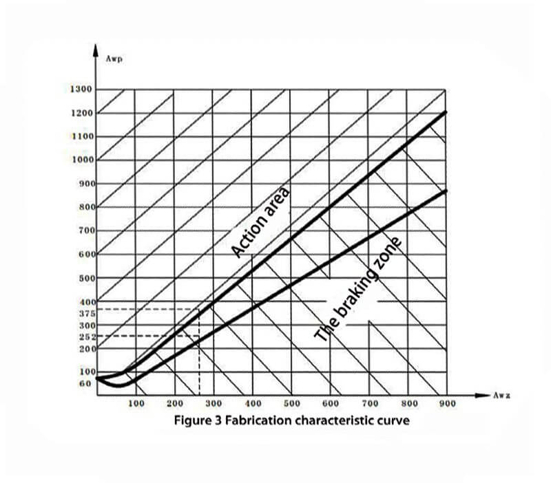
4. The braking coefficient Kz, determined by the ratio of the operating current to the braking current, can vary in a wide range. The braking characteristic AWp= F (AWz) in Figure 3 is its limit range, which is related to the phase Angle between the working current and the braking current, but should not exceed the range of the curve at any Angle.
5. The reliability coefficient (the ratio between the sine action current of the relay when the primary action current is equal to 5IDZ and the sine action current when the primary action current is equal to IDZ) shall not be less than 1.35.
6. When the operating current is 3 times, the operating time of the differential relay shall not be more than 0.035s.
7. The relay has a moving contact. In the dc circuit with inductive load (its time constant is no more than 5x10s), and when the voltage is no more than 220V and the current is no more than 2A, the contact's disconnect capacity is 50W.
8. In normal working condition, when the current is 5A and the braking winding of the converter is put in with all turns, the single-phase power consumption of the relay shall not be greater than 8.5VA.
9. The converter works, and the balance and brake windings can pass through the current 10A for a long time.
10. Dielectric strength: the circuit of the relay shall be able to withstand 2kV, 50Hz AC voltage for min without breakdown or flashover phenomenon between exposed non-charged metal parts.
11. The winding data of the relay are shown in Table 1.
|
Winding |
绕组数据 |
Note |
|
Work |
Wp= 20 turn Φ1.81 |
|
|
Balance I and II |
Wy= 19 turn/pc Φ1.81 |
|
|
Brake |
2 x Wz= 2 x 14 turn Φ1.81 |
|
|
Secondary |
2 x Wz= 2 x 24 turn Φ1.45 |
|
|
Operating element DL-11 relay |
2 x W= 2 x 500 turn Φ0.38 |
Two coils in parallel |
12.The outline and hole size of the relay are shown in Figure 1 attached to page 292 of this manual
Message feedback
News Center
Naidian Group is an electronic timer manufacturer and digital timer supplier, providing high-power relays, electronic time relays, digital timer relays, DC to AC solid state relays, and digital display timer relay knowledge popularization.
On February 26, the production of NPOWER Group resumed. The director and manager of our company personall...
A digital time relay provides precise timing for control circuits — delay, interval, off-delay, or cyclic...
A solid state relay lasts longer with no moving parts to wear. Lifespan depends on thermal management — p...
Motor inrush current (5‑10× running) welds relay contacts. Derate contact rating 5‑7×, use AgSnO₂ for AC,...

GET A QUOTE