Phone number:0086-0577-61731588
Fax:0086-0577-61731588
Cell phone:+86 18072180777
Wechat:+86 18072180777
Website:www.china-relay.com
Zhiguang Industrial Zone, Liu Town, Yueqing, Zhejiang, China
Rated current :5A(50Hz)
Ampere turns :60±4
Setting range:
Two-winding generator 1.55 ~ 12A
Three-winding transformer 3 ~ 12A
Reliability coefficient :5 times ≤1.35 times A2 ≤ 1.2a
Power consumption :≤16VA
Contact form: move and close
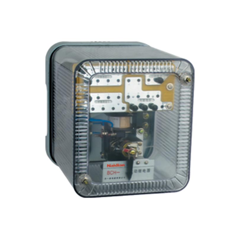
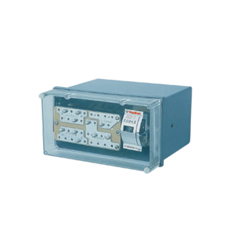
Installation method: HK-7 shell is adopted
Usage
The differential relay is used as a two-winding and three-winding power transformer and a single-phase differential protection for alternators.
The relay prevents the protection from acting non-selectively by unstable transition current in a non-fault state (crossing short-circuit current or when the transformer closes without load).
mmary of structure
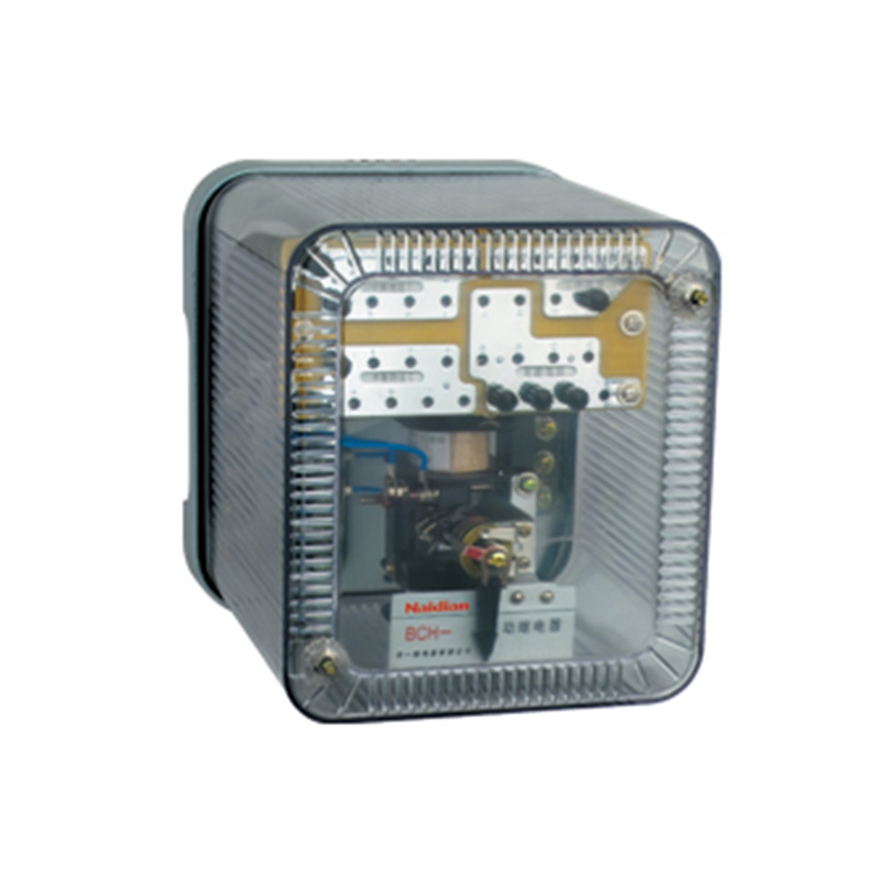
The relay consists of actuator electromagnetic current relay DL-11 and intermediate fast saturated converter.
The relay has short circuit winding, which constitutes some of the main technical performance of differential relay, such as DC magnetic bias characteristics, the performance of auto-converter to eliminate the unbalanced current effect, etc.
All the windings of the fast saturated converter are made with taps so that the parameters of the relay can be stepped.
When a bCH-2 relay is used to protect a power transformer, the number of turns of the balance winding is selected according to the condition that the number of turns of all windings should be equal in the event of a short circuit crossing.
When a two-winding transformer is protected with a relay, the operating current can be adjusted over a more detailed range, as the two balance windings can then be used.
Executive components and put inside a shell of the converter, in order to facilitate the actuators check the need of adjustment and test features of the converter, actuators of coil and the secondary winding of current transformer, balance and working windings is thought by connecting plate connection, thus it can be connected or disconnected when adjusting test of the corresponding circuit.
Technical data
1. Rated current 5A, rated frequency 50Hz.
2. The initial ampere turns of the relay is 60+4.
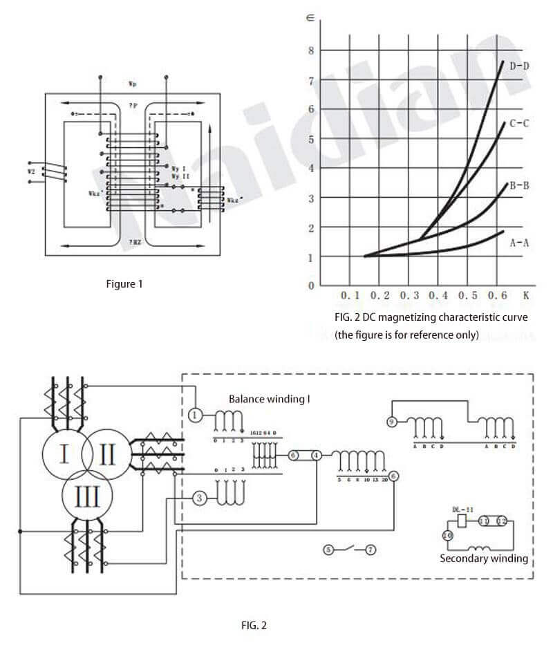
3. Dc magnetic characteristic curve of the relay 9(As shown in FIG. 3)∈=f(K) for subsection adjustment;
The ratio of the K-DC component to the corresponding AC action value.
∈- the ratio between the ac operating current of a relay with a DC component and the ac operating current without a DC component.
FIG. 3 shows a ∈= F (K) curve cluster when the short winding is connected with different turns. When K=0.6, corresponding to each short circuit coil tap,∈ values according to the following provisions:
Short-circuit winding extraction and research location: ∈ : a-A, 1.6+0.13;B - B, 3 + 0.24;C - C, 5 + 0.38;D - D, 7 + 0.56;
4. The reliability coefficient shall be no less than 1.35. The reliability coefficient shall be determined according to the following method: set the operation current of the relay as Id, and the operation current of the corresponding actuator dL-11 relay as I1;Then turn the pointer and tighten the hairspring, so that the action current of the differential relay is 5Id, and then measure the corresponding action current i5 of the actuator, and calculate the reliability coefficient according to the following calculation:
Kk= i5/i1
5. When the operating current is 3 times, the operating time of the differential relay shall not be greater than 0.035s.
6. When the voltage does not exceed 220V and the current does not exceed 2A, the relay contact disconnect capacity is 50W in the DC inductive load (time constant is 5x10s) circuit.
7. At the rated current, when the balance winding (I or II) and the turns of the working winding of the relay are all connected, the single-phase power consumption of the relay shall not be greater than 16VA.
8. When the surrounding medium temperature is +40℃, the working winding and one balance winding of the relay shall be able to pass 10A current for a long time, and the temperature rise shall not exceed 65℃.
9. Dielectric strength: each circuit of the relay shall withstand 50Hz, 2kV AC voltage for 1min between exposed non-charged metal parts without breakdown or flashover.
10. When the turns of each winding are all connected and the short-circuit winding is connected at a-A position, their impedance values are shown in Table 1.
Table 1
|
Winding |
Under the current value of the following (A) and impedance Z (Ω) |
Dc resistance( Ω) |
||
|
3 |
5 |
10 |
||
|
Work |
0 . 32 |
0 . 28 |
0 . 19 |
0 . 04 |
|
Balance I, II |
0 . 3 |
0 . 27 |
0 . 18 |
0 . 042 - 0 . 044 |
11.The winding data of relay are shown in Table 2
Table 2
|
Winding |
Winding data |
Note |
|
Work |
Wp=20 turn Φ1.56 |
|
|
Balance I and II |
Wy=19 turn/pc Φ1.56 |
|
|
Short circuit (middle column) |
W'Kz=28 turn Φ1.45 |
|
|
Short circuit (side column) |
W'''Kz= 28 turn Φ1.45 |
|
|
secondary |
W2=48 turn Φ1.0 |
|
|
Operating element DL-11 relay |
2W=2x500 turn Φ0.38 |
Two coils in parallel |
The outline and hole size of the relay are shown in FIG. 1
Message feedback
News Center
Naidian Group is an electronic timer manufacturer and digital timer supplier, providing high-power relays, electronic time relays, digital timer relays, DC to AC solid state relays, and digital display timer relay knowledge popularization.
On February 26, the production of NPOWER Group resumed. The director and manager of our company personall...
A digital display time relay — ±0.1% accuracy, no drift. LED display, 0.01s–99h range. Reliable timing fo...
A digital time relay provides precise timing for control circuits — delay, interval, off-delay, or cyclic...
A solid state relay lasts longer with no moving parts to wear. Lifespan depends on thermal management — p...

GET A QUOTE