Phone number:0086-0577-61731588
Fax:0086-0577-61731588
Cell phone:+86 18072180777
Wechat:+86 18072180777
Website:www.china-relay.com
Zhiguang Industrial Zone, Liu Town, Yueqing, Zhejiang, China
Rated current :5, 10A
Action current :5A: (2, 2.5, 3, 3.5, 4, 4.5, 5A)
10A: (4, 5, 6, 7, 8, 9, 10A)
Return coefficient :≥0.85
Transient multiple :2-8 times
Setting time of 10 times of action current :11, 15: 0.5 ~ 4S, 12: 2 ~ 16s
13:2 ~ 4 s 14, 16:8 to 16 s
Power consumption :≤15VA
Contact form: move close, move break, two action close, one conversion
Installation method:
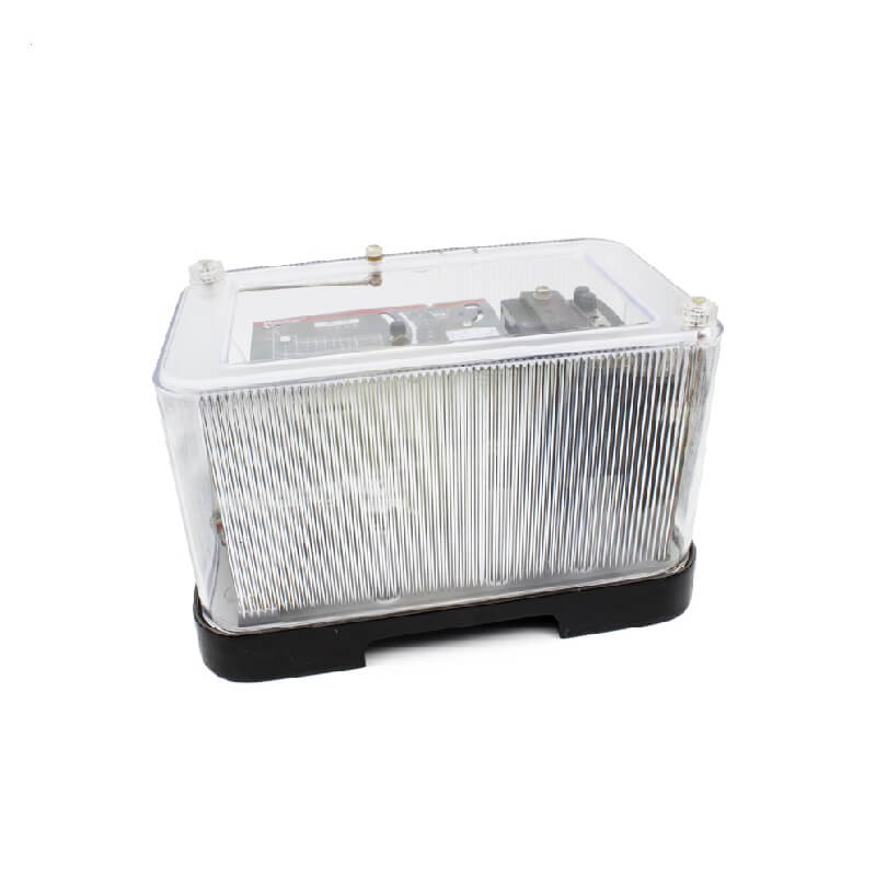
The external size is 243×148×160mm
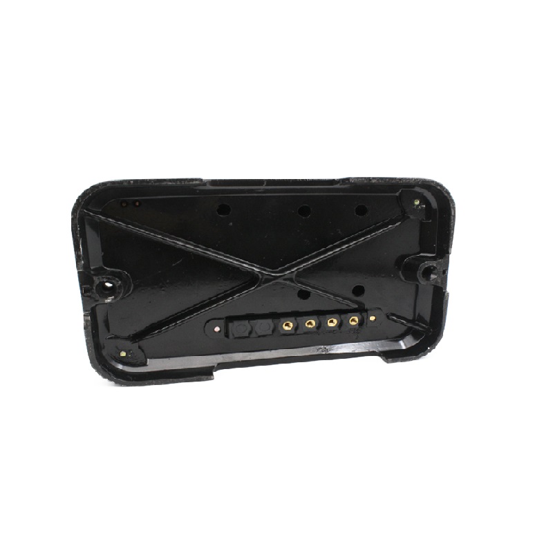
Board front and board back wiring
Usage
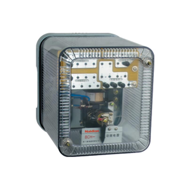
GL-10,GL-20 series inverse time over current relays (hereinafter referred to as relays) have inverse time limit characteristics and are used in relay protection circuits of main equipment such as motors, transformers and transmission and distribution systems. When the main equipment or power transmission and distribution system has over-load and short-circuit fault, the relay can reliably operate or send signals according to the predetermined time limit to remove the fault part and ensure the safety of the main equipment and power transmission and distribution system.
The working principle
The working principle of relay is compound type, which consists of induction type and electromagnetic type which share a coil.When the coil of the relay carries an ac current, two magnetic flux with a certain phase difference are generated in the shielded and unshielded parts of the core.The flux interacts with the eddy currents induced in the disk to produce a torque on the disk.At 20-40% of the operating current setting, the disk begins to rotate.At this point, because the fan tooth and worm do not bite, so the relay does not operate.
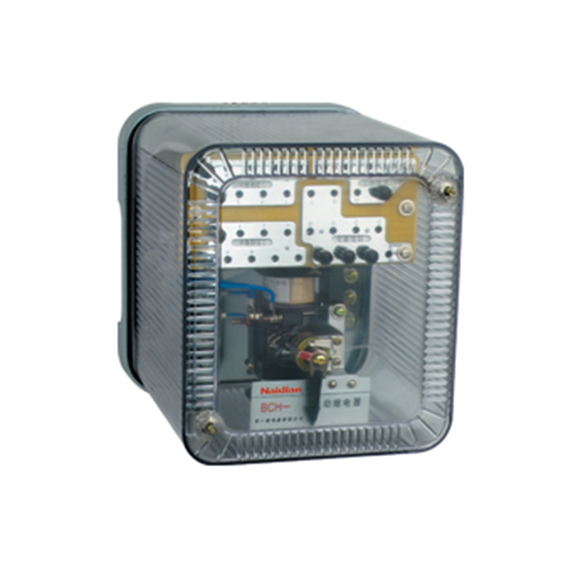
When the current in the coil increases to the setting current, the electromagnetic moment is greater than the reaction moment of the spring and the frame rotates, so that the fan teeth and worm bite, the fan teeth rise.At this time, the moving iron of the relay will reduce the air gap on the right side of the guide magnet and increase the air gap on the left side under the push of the fan tooth tip rod.Thus the moving iron is pulled together by the guide magnet to make the relay contact operate.
When the current in the relay coil is set, the action time limit of the induction element is inversely proportional to the square of the current.With the increase of the current, the permeability of the magnetic body, the duration of action gradually tends to be fixed.When the current in the coil is greater than a certain current multiple, the electromagnetic element acts instantaneously, so the action time limit of the relay has the characteristic of inverse time delay.
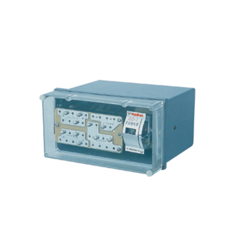
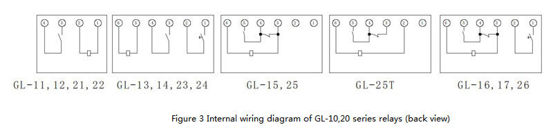
Gl-11,12,21,22 relays are provided with a single action closing main contact (or a single action breaking main contact, which needs to be customized) and have both inverse time limit function and transient function.
Type GL-13,14,23, and 24 relays are provided with a single action closing main contact (or a single action breaking main contact, which needs to be customized) and a delay signal contact operated by the induction element. The main contact suction has the transient function and no inverse time limit function, while the signal contact only has the inverse time limit function and no transient function.
Gl-15, type 25 relays have a strong transition (close first, break later) main contact with both inverse time and transient functions.
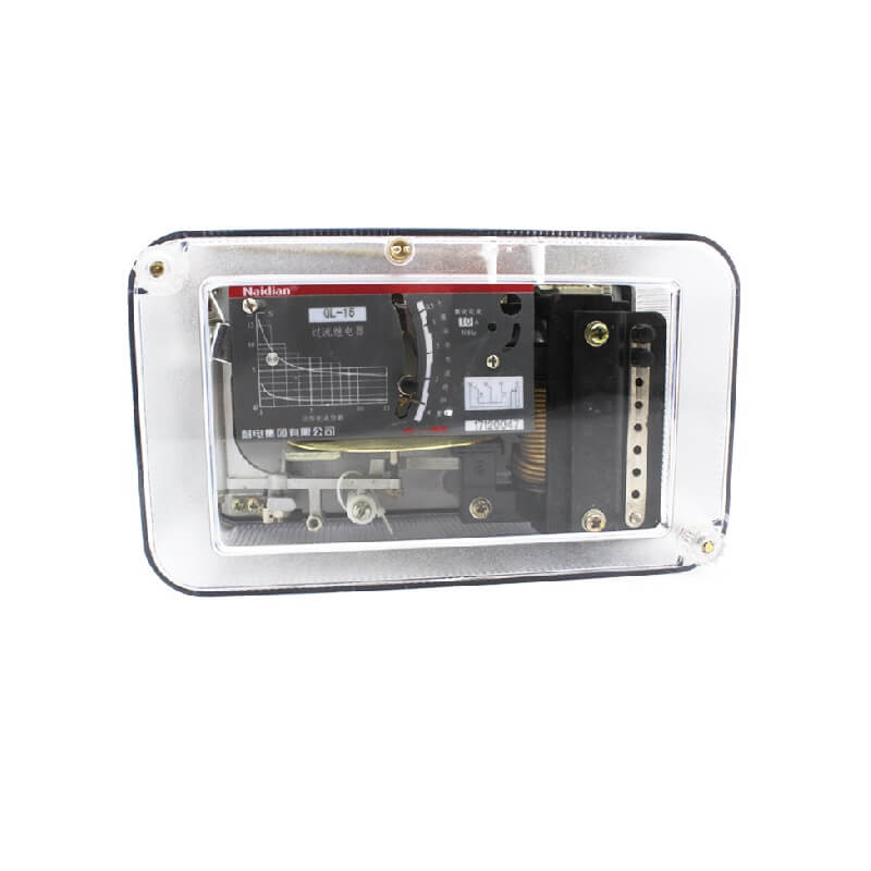
The GL-16 type 26 relay has a strong transition main contact and a delay signal contact operated by an induction element.The main contact of strong transition conversion only has the transient function and no inverse time limit function, while the signal contact only has the inverse time limit function and no transient function.
The GL-17 relay has one strong transition main contact and one delay signal contact.The main contact of strong transition conversion has both instantaneous function and anti-time limit function, while the signal contact only has anti-time limit function and no transient function.
The outstanding function of the strong transition primary contact mentioned above is to ensure that the CT secondary circuit is not open during relay operation.
The technical requirements
1. The rated current and setting range of relay are shown in Table 1.
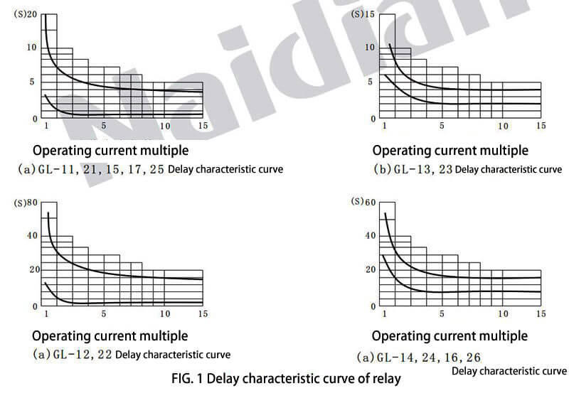
2. The delay characteristic curve of the relay is shown in Figure 1.
3. The long-term allowable current of the relay coil is 100% rated current.
4. The return coefficient of relay for GL - 11,12,21,22 type should not be less than 0.85, the GL - 13,14,15,16,17,23,24,25,26 should not be less than 0.8.
5. When the current is the setting current of the relay, the power consumption of the relay shall not be greater than 15VA.
6. Contact performance
A. Function of moving-closing main contact
The main moving-on contact can be switched on dc or AC 5A when the voltage is no more than 250V, but the circuit disconnected should be acted on by other contacts (such as auxiliary contacts opened and closed).
B. Performance of main contact for dynamic breaking
Dc sensible circuit (GL 10 GL 20xlGLJDq 7=5ms), U≤250V, I≤0.5A, 50W;Communication (cos = Φ 0.4) circuit;U≤250V, I≤2A, 250VA.
If the accused of circuit system by the inverter power supply and main contact with relay in parallel, and when the current is 4 a, the total impedance is not greater than 4 Ω, the main contact in the relay
|
Model |
Rated Current(A) |
Setting value |
Rated frequency(Hz) |
||
|
Current action(A) |
10 times the action time of the current current(S) |
Setting multiple of moving current |
|||
|
GL-11/10 , GL-21/10 GL-15/10 , GL-17/10 GL- 25/10 |
10 |
4 , 5 , 6 , 7 , 8 , 9 , 10 |
0.5,1,2,3,4 |
2 - 8 |
50 |
|
GL-11/5 , GL-21/5 GL-15/5 , GL-17/5 GL-25/5 |
5 |
2,2 . 5,3,3 . 5,4,4.5,5 |
|||
|
GL-12/10 , GL-22/10 |
10 |
4 , 5 , 6 , 7 , 8 , 9 , 10 |
2 , 4 , 8 , 12 , 16 |
||
|
GL-12/5 , GL-22/5 |
5 |
2,2 . 5,3,3 . 5,4,4.5,5 |
|||
|
GL-13/10 , GL-23/10 |
10 |
4 , 5 , 6 , 7 , 8 , 9 , 10 |
2 , 3 , 4 |
||
|
GL-13/5 , GL-23/5 |
5 |
2,2 . 5,3,3 . 5,4,4.5,5 |
|||
|
GL-14/10 , GL-24/10 GL-16/10 , GL-26/10 |
10 |
4 , 5 , 6 , 7 , 8 , 9 , 10 |
8 , 12 , 16 |
||
|
2,2 . 5,3,3 . 5,4,4.5,5 |
|||||
|
GL-14/5 , GL-24/5 |
5 |
4 , 5 , 6 , 7 , 8 , 9 , 10 |
|||
|
GL-16/5 , GL-26/5 |
2,2 . 5,3,3 . 5,4,4.5,5 |
||||
This circuit can be shunt on and shunt off when the current is no more than 50A.
C. Overcurrent conversion main contact performance
Relay over-current conversion main contact control circuit by the power of the converter, and the impedance value when the current is 3.5 A is not greater than 4.5 Ω, when the current 150 A, relay main contact to shunt connected with shunt disconnect the circuit.
D. Signal contact performance
The dynamic and closing signal contact of the relay can be connected or disconnected when the voltage is not more than 250V and the DC inductive circuit whose current is not more than 0.2A or the current is not more than 0.5A
Current circuit.
7. Thermal performance requirements
When the ambient humidity is 40℃, the relay winding coil bears 110% of the rated current for a long time, and its maximum allowable temperature rise shall not exceed 65℃.
8. Insulation resistance is not less than 300 m Ω.
9. All circuits of dielectric strength relay should be able to withstand 2kV(RMS) 50Hz AC test voltage for the shell and the non-charged metal part, as well as the circuits that are not connected electrically, for 1min, without insulation breakdown or flashover.
Life of 10.
Type GL-11-14,21-24 relay has a mechanical life of 5000 times and an electrical life of 500 times.
Type GL-15,16,17,25 and 26 relays have a mechanical life of 500 times and an electrical life of 50 times.
11. It weighs about 4kg.
Debug method
When the structure or performance of the relay is changed due to shock during transportation or other reasons, it is recommended to adjust it as follows.
1. The clearance of main contact is not less than 2mm.In order to prevent contact jitter, moving contacts should contact the limiter before the action for moving contact and after the action for moving break contact.
2. Signal contact clearance is not less than 1.5mm.When the signal contact is just closed, the fan tooth and worm bite should not be less than 2 teeth.
3. Transition and conversion of main contact
A. In the schematic diagram of the contact system, the pressure of the main contact of the moving break is not less than 7g, which can be achieved by bending contact sheet 5 (see Figure 2), and the contact gap after disconnection is not less than 2mm.
B. The clearance of the main contact of the movable contact should not be less than 1.5mm.
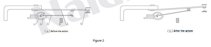
C. Before operation, contact sheet 3 rests on the stop, and the distance between spring sheet 2 and contact sheet 3 is 0-1mm.
4. Axial activity of the frame and the turntable is 0.1-0.2mm.Relay in the working position and inverted 180° position, the turntable should not touch with the long magnet and magnetic guide pole surface.
5. The occlusion between the fan tooth and the worm is 1/3 to 2/3 of the height of the fan tooth.
6. Transient current can be adjusted by rotating the double current screw to change the air gap between the moving iron and the guiding magnet.
7. Adjust the induction plate and the spring, so that the return current of the action current is the same as the technology.
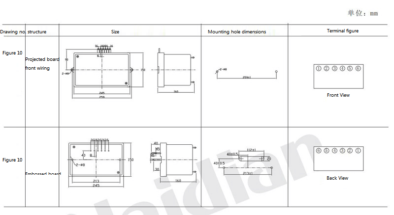
External structure and mounting hole size
The relay adopts a fixed mounting shell, and its external structure and mounting hole size are shown in the attached figure 10.
Message feedback
News Center
Naidian Group is an electronic timer manufacturer and digital timer supplier, providing high-power relays, electronic time relays, digital timer relays, DC to AC solid state relays, and digital display timer relay knowledge popularization.
On February 26, the production of NPOWER Group resumed. The director and manager of our company personall...
A digital display time relay — ±0.1% accuracy, no drift. LED display, 0.01s–99h range. Reliable timing fo...
A digital time relay provides precise timing for control circuits — delay, interval, off-delay, or cyclic...
A solid state relay lasts longer with no moving parts to wear. Lifespan depends on thermal management — p...

GET A QUOTE