Phone number:0086-0577-61731588
Fax:0086-0577-61731588
Cell phone:+86 18072180777
Wechat:+86 18072180777
Website:www.china-relay.com
Zhiguang Industrial Zone, Liu Town, Yueqing, Zhejiang, China

Power supply voltage: 220VAC 50/60Hz;(2) 100-240 vac/DC
Allowable voltage variation range: 90-110% of supply voltage
Power consumption: below 8VA
Input specification: Thermocouple :K, E, J
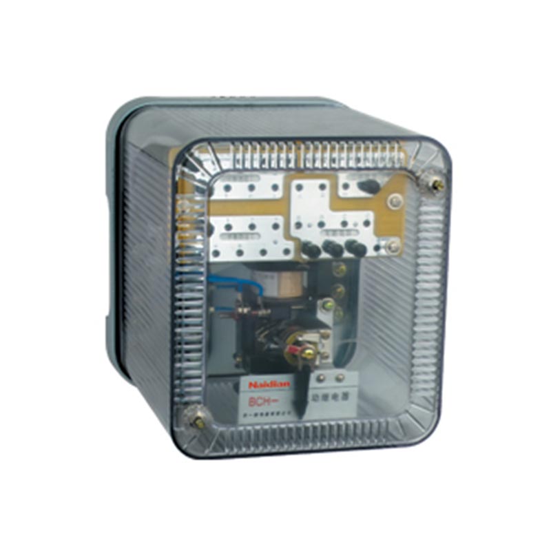
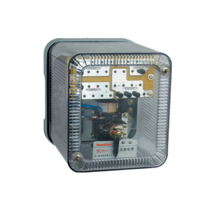
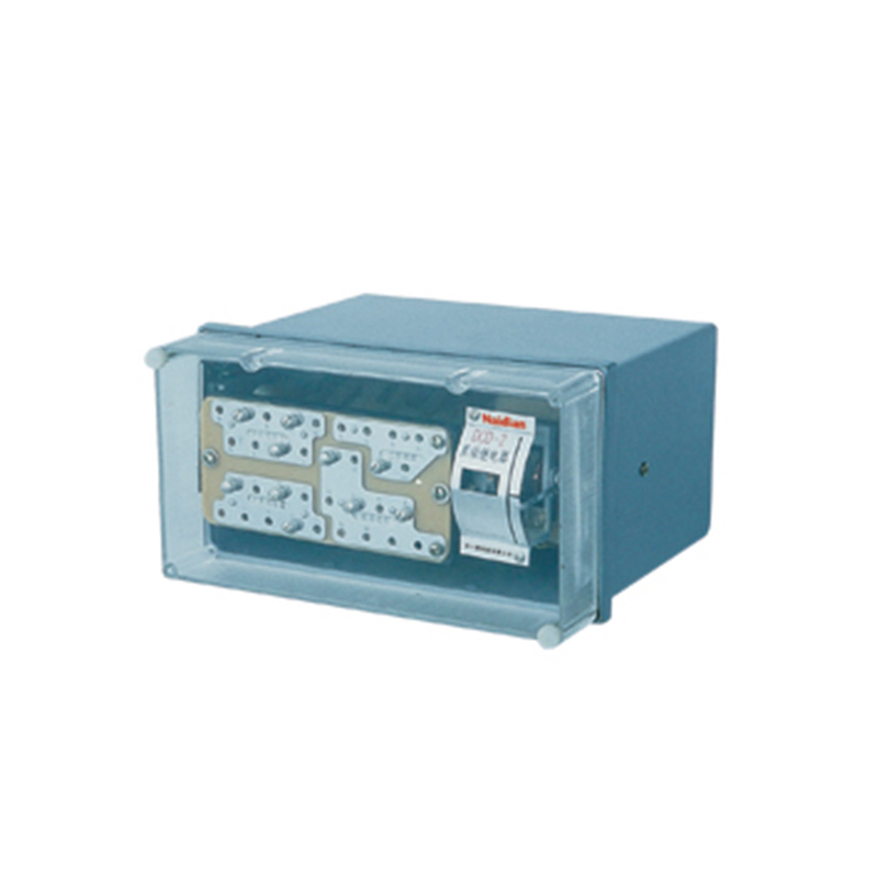
Product Description:
Power supply voltage: 220VAC 50/60Hz;(2) 100-240 vac/DC
Allowable voltage variation range: 90-110% of supply voltage
Power consumption: below 8VA
Input specification: Thermocouple :K, E, J
Thermal resistance :Pt100 Cu50
Display accuracy :±0.5%
Input specification: relay 250VAC 5A one on one off
SSR 12VDC±2V 20mA or less
Analog voltage output (0-5V, 1-5V)
Analog current output (0-20mA, 4-20mA)
SCR Silicon controlled output (zero crossing output, phase shifting output)
Product parameters
|
Power supply voltage |
①220VAC 50/60Hz ②100-240VAC/DC |
|
|
Range of allowable voltage variation |
90-110% of the supply voltage |
|
|
Consumed power |
Below 8VA |
|
|
The input specifications |
Thermocouple |
K E J |
|
Thermal resistance |
Pt100 Cu50 |
|
|
Display precision |
±0.5% |
|
|
The input specifications |
The relay 250VAC 5A is on and off |
|
|
Below SSR 12VDC±2V 20mA |
||
|
Analog voltage output (0-5V, 1-5V) |
||
|
Analog current output (0-20mA, 4-20mA) |
||
|
SCR Silicon controlled output (zero crossing output, phase shifting output) |
||
|
Alarm output |
The relay 250VAC 5A is one NO |
|
|
The control mode |
Bit control, PID control |
|
|
Sampling period |
100ms |
|
|
Relay life |
Mechanical more than 2.5 million times electrical more than 100,000 times |
|
|
Withstand voltage |
2000VAC 50/60Hz 1 min (between terminals and housing) |
|
|
Resistance to vibration |
5~55Hz(cycle 1 minute) amplitude 0.75mm X,Y,Z all directions for 2 hours |
|
|
Insulation impedance |
More than 10 om Ω MEGA (500 VDC) |
|
|
anti-interference |
Simulated square wave generator interference (pulse width 1 m) ±2KV R phase S phase |
|
|
Power failure memory |
About 10 years (non-volatile semiconductor memory) |
|
|
The surrounding environment |
Operating ambient temperature |
When stored at -5~40℃ :-10~50℃ |
|
Ambient humidity in use |
35 ~85% storage :35 ~85% |
|
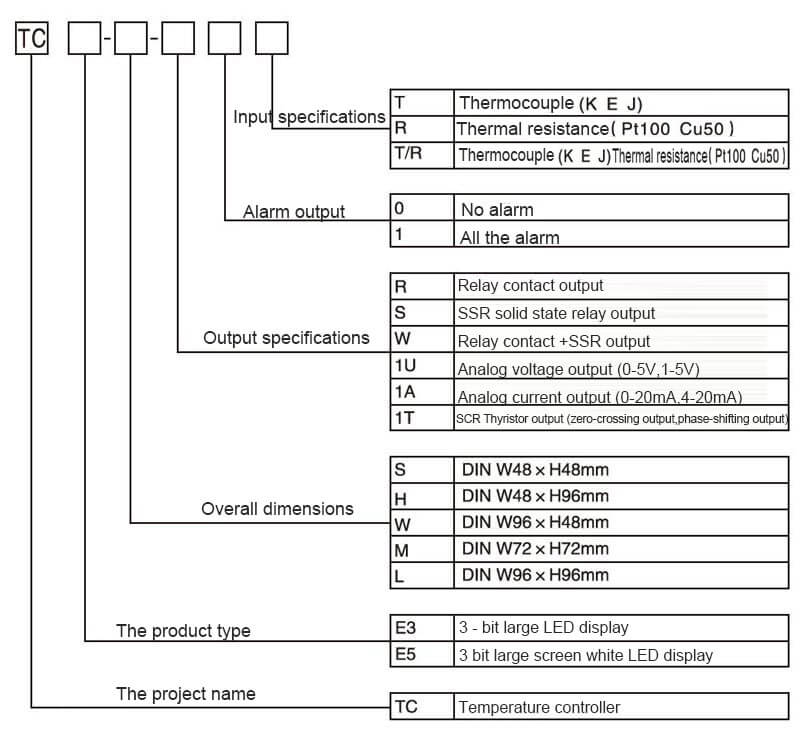
Model code
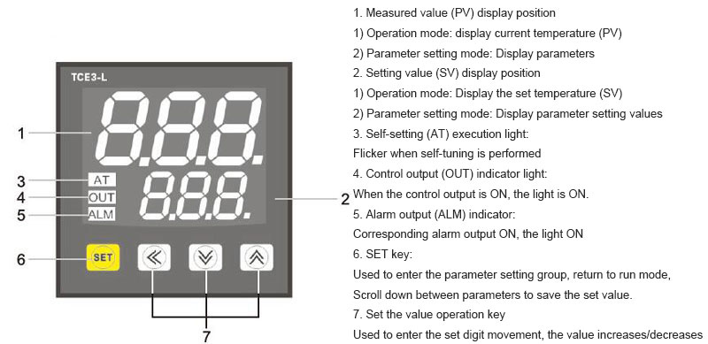
Name of each part
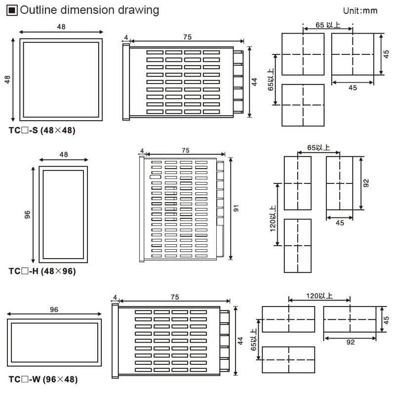
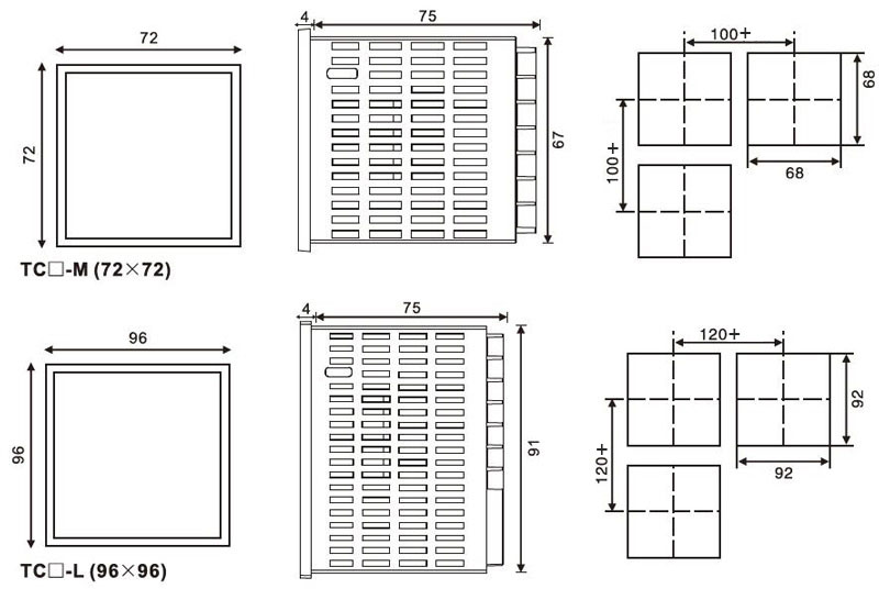
Exterior dimension drawing
Message feedback
News Center
Naidian Group is an electronic timer manufacturer and digital timer supplier, providing high-power relays, electronic time relays, digital timer relays, DC to AC solid state relays, and digital display timer relay knowledge popularization.
On February 26, the production of NPOWER Group resumed. The director and manager of our company personall...
Motor inrush current (5‑10× running) welds relay contacts. Derate contact rating 5‑7×, use AgSnO₂ for AC,...
An electronic time relay eliminates temperature drift, offers repeatability under 5 ms, accepts universal...
Discover the NDS4-P digital time relay with superior precision timing capabilities. Features wide voltage...

GET A QUOTE