Phone number:0086-0577-61731588
Fax:0086-0577-61731588
Cell phone:+86 18072180777
Wechat:+86 18072180777
Website:www.china-relay.com
Zhiguang Industrial Zone, Liu Town, Yueqing, Zhejiang, China
Usage
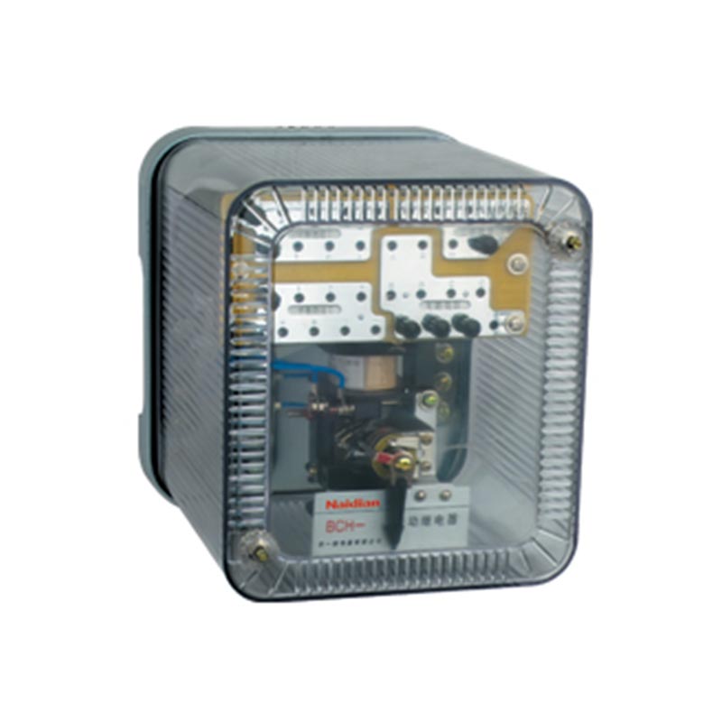
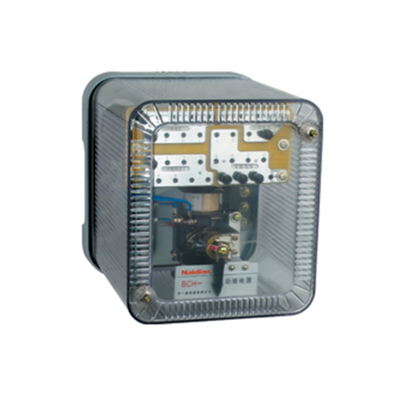
LB-8 type broken phase blocking relay (hereinafter referred to as the relay) is used in the protection equipment consisting of generator or generator. When phase breaking occurs at the two flashier side of the voltage transformer, it will block the protection equipment which may cause wrong action
Structure and working principle
2.1Structure
The relay adopts JK-32K,H and Q-type standardized shell components, with three structural forms of embedded rear wiring (JK-32K), protruding rear wiring (JK-32H) and protruding front wiring (JK-32Q), which can be optional.The external dimensions, installation dimensions and terminal drawings are shown in the appendix.
2.2Working Principle
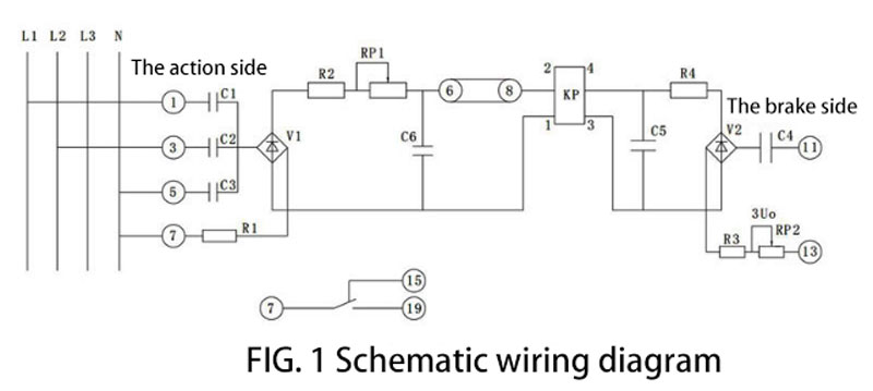
See Figure 1 for the basic wiring diagram of the relay.
The operation principle of the relay is to judge whether the voltage on the secondary side of the voltage transformer is balanced by the vector synthesis of the three-phase input voltage signal is zero, and to judge the cause of three-phase unbalanced voltage on the secondary side of the voltage transformer by the three-phase zero sequence voltage.
When phase break occurs on the secondary side of the voltage transformer, the balanced current input from the operating side flows through the rectifier and is filtered and added to the operating side of the polarization relay. When the current reaches or exceeds the operating current of the polarization relay, the relay operates at the outlet.
In case of external grounding fault or inter-phase short-circuit grounding fault, 3Uo=100V on the braking side makes the polarization relay brake reliably, although voltage input is available on the operating side.
The technical requirements
3.1 Rated line voltage 100V, frequency 50Hz.
3.2 When the symmetrical line voltage of 100V is applied to the operation side of the relay, the operating current of the polarized relay shall not be less than 3mA when one or two phases are open.
3.3 When the symmetric line voltage is applied at 100V(phase voltage is 58V), the unbalanced current in the coil of the polarization relay of relay actuator is not greater than 0.3mA.
3.4 The relay shall be able to brake reliably when the three-phase parallel voltage of 58V is applied on the operating side of the relay and 100V is applied on the braking side of 3Uo.
3.5 When one or two phases are disconnected at the rated line voltage of 100V, the disconnect time of the dynamic break contact of the polarization relay shall not be more than 10ms.
3.6 At the rated voltage of 100V (phase voltage 58V), the power consumed by each phase of the relay shall not be more than 3VA.
3.7 In the DC inductive load circuit (5ms±0.75ms) with voltage no more than 250V and current no more than 0.2a, the relay contact disconnect capacity is 20W.
3.8 in the environmental temperature of 40 ℃, relative humidity of 85%, under the condition of open circuit voltage of 500 v test instrument is used to test, the conductive circuit of shell, and there is no contact of electric conductive circuit between the insulation resistance shall be not less than 4 m Ω.
3.9 All circuits of the relay shall be able to withstand tests of 50Hz, 2kV AC voltage and lasting for 1min without insulation breakdown or flasticity.
3.10 The electric life of the relay is 1x10 times.
3.11 The weight of the relay is about 3kg.
Debug method
4.1 Inspection of capacitance and polarization relay
A. Check the capacitance, and the error should be less than 5%.
B. Check the polarity and operating current of the polarization relay, and the operating current should be within the range of 2.6-2.7mA.
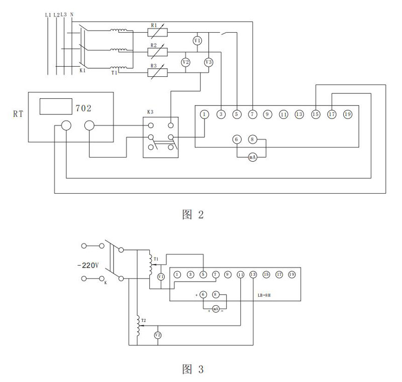
4.2 Make the wiring according to the debugging wiring diagram shown in Figure 2, close K1,K2 and K3, and adjust the auto-transformer T1 so that the output line voltage of the three-phase auto-transformer T1 is 100V (or 58V for each phase).4.3 When K2,K3 or K3 are disconnected, the relay shall be able to work reliably.At this time in terminal ○, measured through the polarization relay KP action coil current should not be less than 3mA.If not, the potentiometer RP1 should be adjusted to meet the requirement. At this time, the disconnect time of the relay's dynamic break contact should not be more than 10ms. In addition, 4.4 pieces should be rechecked.
4.4 Switch on K1,K2 and K3, and the unbalanced current in the polarization relay measured between terminals ○ and ○ should not be greater than 0.3mA.If not, replace the capacitor.
4.5 Wiring according to Figure 3, first add single-phase voltage of 58V between terminal ○, relay action, and then add ○ through the terminal, the same phase voltage of 100V, the relay should return reliably, if not in accordance with RP2 shall be adjusted.
Supply package
Are supplied with the products;
A. Product qualification certificate;
B. Product operation manual.
C. Product installation accessories
Figure 2, Figure 3
Message feedback
News Center
Naidian Group is an electronic timer manufacturer and digital timer supplier, providing high-power relays, electronic time relays, digital timer relays, DC to AC solid state relays, and digital display timer relay knowledge popularization.
On February 26, the production of NPOWER Group resumed. The director and manager of our company personall...
A digital display time relay — ±0.1% accuracy, no drift. LED display, 0.01s–99h range. Reliable timing fo...
A digital time relay provides precise timing for control circuits — delay, interval, off-delay, or cyclic...
A solid state relay lasts longer with no moving parts to wear. Lifespan depends on thermal management — p...

GET A QUOTE