Phone number:0086-0577-61731588
Fax:0086-0577-61731588
Cell phone:+86 18072180777
Wechat:+86 18072180777
Website:www.china-relay.com
Zhiguang Industrial Zone, Liu Town, Yueqing, Zhejiang, China
Rating: 100 50
Add 100V symmetric voltage,
Disconnect time of actuating broken contact: ≤0.01
Power consumed: ≤50VA
Contact breaking capacity: 200VA
40 w (T = 50 ms)
Operating current: 1.7~1.8
Return coefficient: ≥0.3
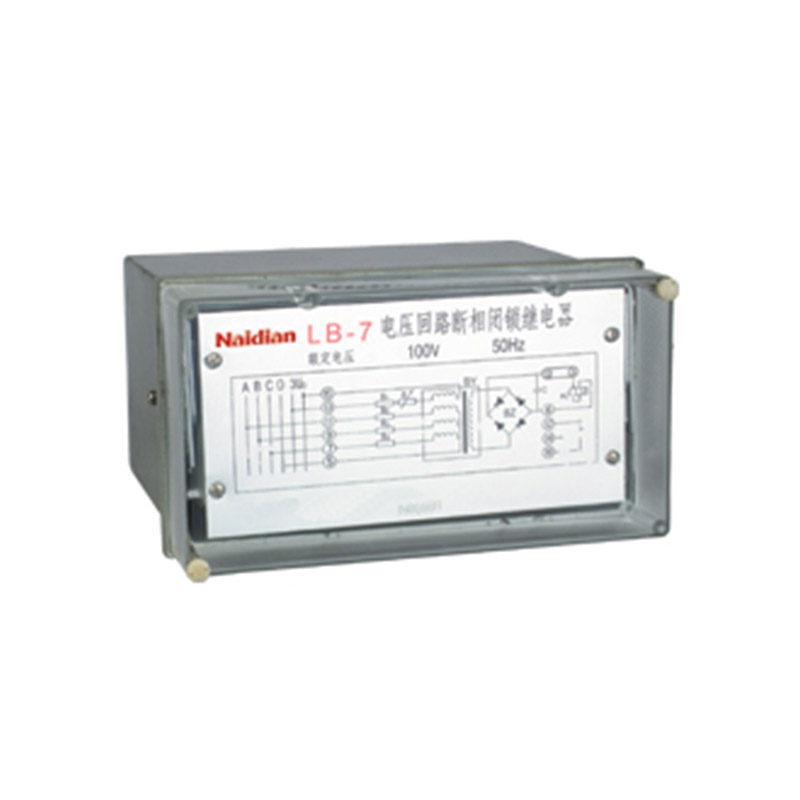
Usage
LB-7 locking relay (hereinafter referred to as the relay) is used to prevent the grounding switch when the high-voltage bus is live in power plant and substation.
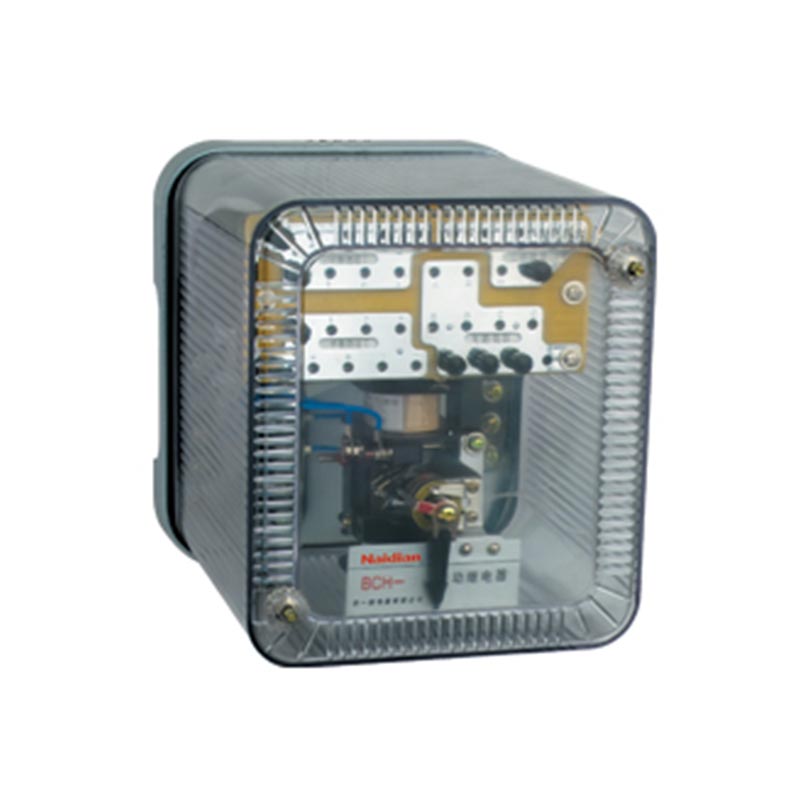
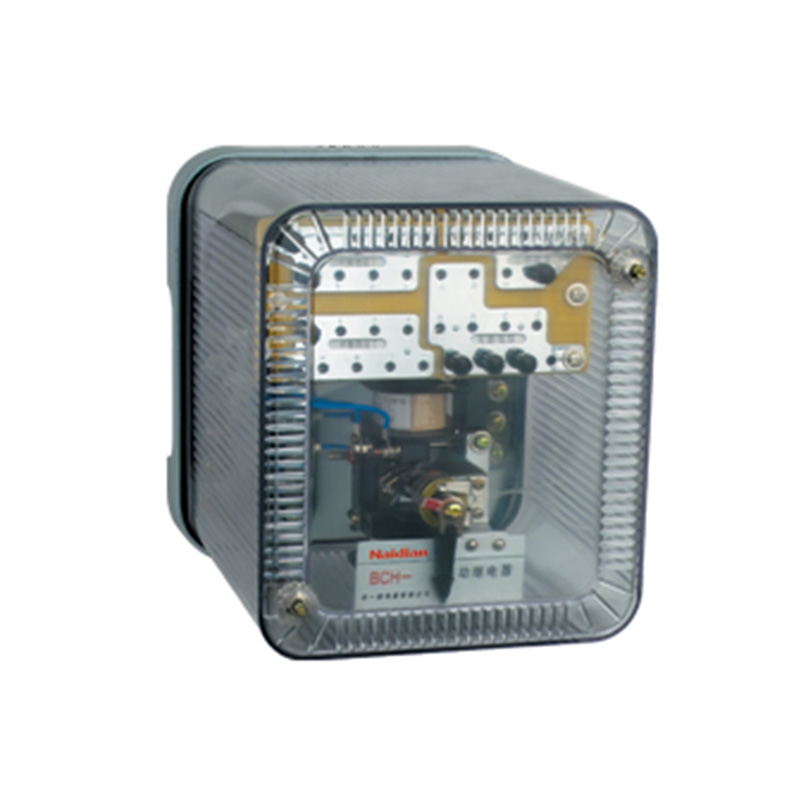
Structure and working principle
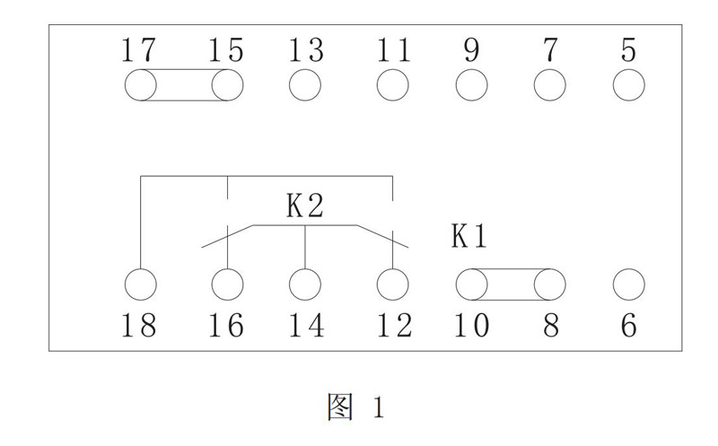
The relay adopts JK-32K, H and Q-type standardized shell components, with three structural forms of embedded rear wiring (JK-32K), protruding rear wiring (JK-32H) and protruding front wiring (JK-32Q), which can be optional.See the appendix for its outline and size of mounting holes, and see Figure 1 for wiring of backside terminals.
2.2Working Principle
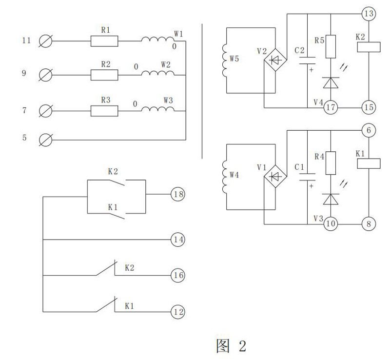
The principle of the relay is shown in Figure 2.
a. The relay shall be constructed according to the principle of rectifier type.Its components include transformer, resistor, rectifier bridge, filter capacitor, polarization relay and indicator light.
b. The transformer used for the relay is a five-winding transformer.The original three sides are connected by A star, in which the polarity of Phase A is opposite, so when the three-phase symmetrical voltage is applied, the magnetic flux sum is not zero. The secondary winding has voltage output, and two polarization relays are driven by rectification and filtering.The contacts of two polarized relays are connected to each other in series to realize their output doublealization.
c. If one or two phases are broken, the transformer also has secondary voltage output and the relay operates reliably;
d. The relay is connected to the secondary side of the voltage transformer on the high-voltage bus of the power plant and the substation. When the high-voltage bus has no power, the relay is released, the dynamic breaking contact of the polarization relay is closed, the blocking is removed, and the grounding switch is allowed.
The technical requirements
3.1 Rated voltage: ac 100V,50Hz.
3.2 The rated voltage of three-phase AC applied by the relay is 100V(phase voltage 58V) and the relay operates reliably when one or two phases are broken.Return reliably when power is cut off.
3.3 When the three-phase rated voltage of the relay is applied at 100V, the current flowing in the polarized relay of relay operating elements shall not be less than 5mA.
3.4 The rated voltage applied by the relay shall be broken A phase and the current flowing through the polarized relay shall not be less than 2.5mA.
3.5 The rated voltage is applied to the relay, and its operating time is not more than 45ms at room temperature.
3.6 The rated voltage applied by the relay shall not be more than 5VA for each phase.
3.7 When the ambient temperature is +40℃ and there is electricity (one phase, two phase or three phase), the relay can withstand 1.1 times the rated voltage for a long time, and the temperature rise does not exceed 65K.
3.8 When the voltage is no more than 220V and the current is no more than 0.2a, the relay contact capacity is:
A. Can disconnect 20W in dc inductive load circuit (=5ms±0.75ms);
B. 30VA can be disconnected in ac circuit (cos =0.4±0.1).
3.9 all relay circuit of the leakage of charged without contact each circuit on metal parts and electrical insulation resistance between not less than 300 m Ω, in not less than 4 m Ω alternating hot and humid conditions.
3.10 All circuits of the relay shall withstand ac 50Hz, 2kV, 1min test without insulation breakdown or flasticity between the non-connected circuits on the exposed non-charged metal parts.
3.11 The electrical life of the relay shall not be less than 10 times, and the mechanical life shall be 10 times.3.12 The relay weight is 3kg.
Debug method
4.1 Debugging of polarization relay, apply AC voltage slowly, the operating current measured on terminals 8 and 10, 15 and 17 is 1.7-1.8mA, and the return current is not less than 0.9mA.
4.2 The rated voltage shall be applied to the relay commissioning, and the relay shall meet the requirements of Article 3.2-3.5.
Message feedback
News Center
Naidian Group is an electronic timer manufacturer and digital timer supplier, providing high-power relays, electronic time relays, digital timer relays, DC to AC solid state relays, and digital display timer relay knowledge popularization.
On February 26, the production of NPOWER Group resumed. The director and manager of our company personall...
A digital display time relay — ±0.1% accuracy, no drift. LED display, 0.01s–99h range. Reliable timing fo...
A digital time relay provides precise timing for control circuits — delay, interval, off-delay, or cyclic...
A solid state relay lasts longer with no moving parts to wear. Lifespan depends on thermal management — p...

GET A QUOTE