Phone number:0086-0577-61731588
Fax:0086-0577-61731588
Cell phone:+86 18072180777
Wechat:+86 18072180777
Website:www.china-relay.com
Zhiguang Industrial Zone, Liu Town, Yueqing, Zhejiang, China
Rated current :5A(50Hz)
Ampere turns :60±4
Setting range:
Two-winding generator 1.55 ~ 12A
Three-winding transformer 3 ~ 12A
Contact form: move and close
Reliability coefficient :5 times ≤1.35 times A2 ≤ 1.2a
Power consumption :≤16VA
Action time;Triple action AC ≥0.035s
Winding long term current :10A
The external dimension is A32K shell
Usage
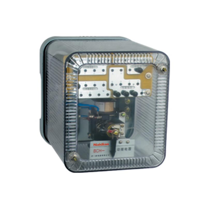
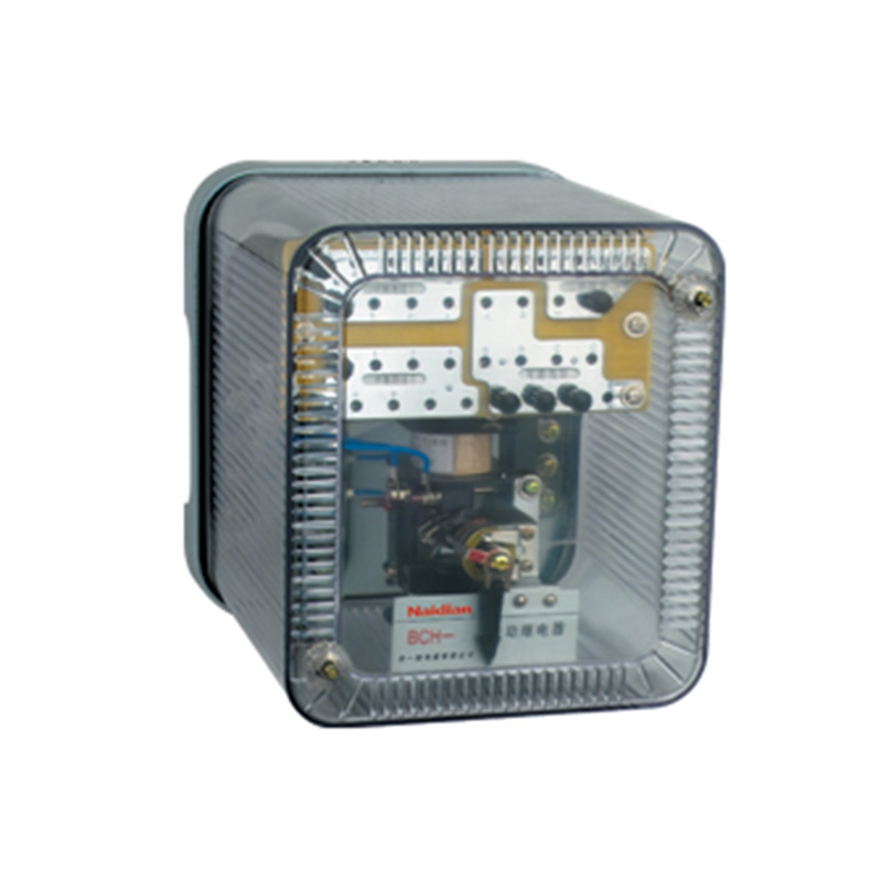
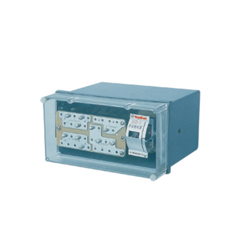
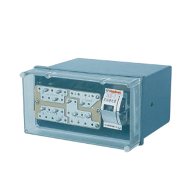
DCD-2A differential relay (hereinafter referred to as the relay) is used for primary protection in single-phase differential protection lines of two or three winding power transformers and ac generators.
The relay prevents transient currents from occurring in non-fault states. For example, when the power transformer is closed by air or after the crossing short circuit is removed, a large magnetizing inrush current occurs when the voltage is restored, and its instantaneous value is often 5-10 times of the rated current.At this time, the differential protection should not misoperate, but in the case of short-circuit in the zone, it can quickly move to eradicate the fault.
Structure and working principle
1.Structure
The relay consists of a highly sensitive, highly reliable electromagnetic actuator with a moving contact and an intermediate velocity saturated converter.The actuator is an electromagnetic relay, which is used as an outlet element in the relay.
The intermediate velocity saturated converter has short circuit winding and balance winding, which constitute some of the main technical properties of the differential relay, such as the DC magnetic bias characteristic to eliminate the unbalanced current effect of the self-coupling converter performance.
The converter's magnetic body is composed of "E" shaped magnetic discs, with balance winding I,II and short circuit winding.In addition, the short-circuit winding on the middle column and the short-circuit winding on the right side column are connected through a porcelain plate potentiometer, and the secondary winding is placed on the other side column of the magnetic body.The distribution of windings in the magnetite is shown in Figure 1.The internal connecting mother of the relay and the principle connecting mother of its protective three-winding power transformer are shown in Figure 2.With balanced winding and taps at every turn, it is easy to adjust to eliminate the effect of unbalanced current caused by the transformer ratio.A power transformer having two balanced windings enables the relay to protect the three windings.
The action current and balancing action can be adjusted by adjusting the working winding, and the turns of the balancing winding can be adjusted in a wide range.Dc magnetic bias characteristics can be set by changing the resistance of the porcelain plate potentiometer in the relay.
The structure, shape, installation size and connection of relay terminals are shown in Figure 6.
2.Principle
The basic principle of relay is to use the non-periodic component of the transient current in the non-fault state to magnetize the converter's magnetic body and improve its saturation degree, thus forming the role of unbalanced current in avoiding excitation inrush current and crossing fault. Its corresponding characteristic curve is a cluster ∈=f(K) for dc magnetic bias characteristic.The working winding is connected with the protected differential loop; The balance winding can be connected to the loop or the working loop according to the actual needs.
A converter with a short-circuit winding is characterized by the use of an aperiodic current to magnetize the magnetite.FIG. 3 shows the electromagnetic process inside the magnetic conductivity body. When the power transformer closes without load, the inrush current with a large instantaneous value flows through the working winding, and the inrush current waveform has a magnetic flux biased to the time axis.They produce two different reactions in the short-circuit line group. Under the action of DC magnetic flux, the magnetic permeability is rapidly saturated, which greatly reduces the magnetic permeability, which greatly worsens the electromagnetic induction conditions between the working winding and the secondary winding, thus significantly increasing the operating current of the relay, which is the so-called DC magnetic bias effect.
The same effect is also produced when the traversing short circuit, in which the current contains an aperiodic component, is removed, and thus prevents the false action when the voltage is restored after the traversing short circuit is removed.The dc magnetic bias characteristic of the relay is represented by the curve cluster ∈=f(K) in FIG. 4.
Where, ∈=Icp/Icpo, the action current multiple is the ratio between the AC action current with dc component and the AC current when the DC component is equal to zero.
K=I-/Icp, migration factor, that is, the ratio of the DC component to the corresponding AC action current, which represents the offset degree of the current waveform to the time axis.
The above ∈=f(K) is a static characteristic of a relay, which is obtained by running both AC and DC current tests in the working winding.The dc current does not change with time, while the value of the non-periodic component of the current decreases with time.
In order to produce a better velocity saturation characteristic, the converter chooses a higher working flux density Bcp in design, but at the same time, in order to ensure the capacity necessary for the reliable operation of the relay, it is stipulated that the reliability coefficient KH is not less than 1.35 when the relay operation current is 5 times the starting value.
The working flux density of the converter is the weight of the magnetic material and the starting operating voltage and operating current.Operating voltage response converter operating flux density;Dynamic power determines the power allocation ratio of the converter, at the same time meet the production requirements, commonality of the actuators is the coil is inductive, under the condition of current transformer is saturated, the secondary induction electric contains significantly higher harmonic filter, so the actuators is a very good higher harmonic filter, it basically reflect fundamental wave converter working magnetic flux density.
The wiring principle of the relay is shown in Figure 2.
Use and maintenance
1. Specification of working winding and balance winding
The setting of the working winding and the balance winding can be carried out by opening the housing.Working winding, balance winding I,II have taps to meet the requirements of a variety of setting values.The following electric setting plate below the number that represents the corresponding winding number.Each winding is divided into two segments, this design can use less taps, more turns array full.Thus making the setting range wide without losing its fine.There are two setting screws in each setting plate of the relay, and each setting screw can be set within its own range.The sum of the numbers marked at the two screw setting positions is the set turns of the winding.
It should be noted that the winding is disconnected when the two setting screws on the same setting plate are not set within their respective ranges or are not connected.
2. Setting of magnetic characteristic curve
When setting magnetic characteristic curve, it is necessary to pull out the relay movement, and then loosen the three big screws that lock the porcelain plate variable resistor on the magnetic characteristic sign plate, so that the knob can rotate freely, and then adjust the magnetic characteristic curve by rotating the knob.
2.1 Set according to the specified curve
The relay has four curves A,B.C.D.The four curves have been carefully adjusted according to the technical requirements before the relay leaves the factory, so it is only necessary to aim the arrow on the knob at the required setting point.
2.2 Setting of special requirements
If the setting curve is within the range of A and D curves but not on the four curves of A.B.C.D, it can be set in the following way.
1) Determine the ∈ value when K=0.6 by the required ∈= F (K) curve.
2) Determine the dc current value to be added during the test.
The working winding is set at 20 turns, the balance winding is set at 19 turns, and then the initial action sinusoidal current value Icpo is measured.By K = 0.6
And K=I/Icpo, calculated dc current I=KIcpo=0.6Icp
3) Determine the location of the disk variable resistor
Icp=∈Icpo [∈ value by 1); Icpo measured by 2)].The working winding and the balance winding are set at 20 turns and 19 turns respectively, and the terminals are added at the same time. The dc current I and AC action current Icp calculated previously are added. The adjustable resistance is adjusted to make the relay action current Icp.
4) If accurate setting is required, make the indicator of the RHEostat knob at the previous setting position not charged for the time being, then repeat each setting step after Section 2) until the setting position of the rheostat is no longer changed.(The initial ampere turns may vary over a small range due to a change in the resistance value of the variable resistor).
After setting the magnetic characteristic curve, fasten the three locking screws evenly.
3. When the relay is used to protect the three-winding power transformer, two balance windings are applied and connected to the two arms of the circulation loop respectively, so that the effect of unbalanced current in the three circulation loops can be balanced. When the relay is used to protect the two-winding power transformer, only one balance winding is needed.Balance under the condition of the unbalance current is larger, the winding is connected to the circulation loop, when the unbalance current is small, or protects the alternator, balance winding can access circuit, to expand the scope of setting value, balance the effect of winding can use two current transformer is determined by the ratio of the secondary current balance coefficient, the balance coefficient of actual application to calculate the number of turns winding access according to figure 6 lines I1, I2, respectively two ct (current transformer) secondary current, and I1 than I2, usually balance winding on the current boom.When the synthetic magnetization of the operating circuit is zero, the effect of the unbalanced current is completely eliminated, and the following equations are obtained:
(I1-I2) WP-i2WY =0 or I1Wp=I2(Wp +WY) (1)
The equilibrium coefficient KY is KY=I1/I2=(Wp+WY)/Wp (2)
4. The initial action of the relay ampere-turns can be adjusted within a small range by means of potentiometer W. During the adjustment, loosen the tightening nut first, and then adjust the potentiometer handle by means of a type screw cutter.
5. During the operation of the relay, it should be noted that the position of the pointer on the nameplate should not be changed.
Technical performance and parameters
1. Rating: rated current 5A, rated frequency 50Hz.
2. When there is no DC component, Awo=60+4 for the initial relay operation.
3. When used to protect three-winding power transformers or alternators, the operating current can be set in the range of 3-12A (Awo=60). For the minimum setting value of the operating current, its maximum balance coefficient is close to 2.
4. When used to protect two-winding power transformers or alternators, the operating current can be set in the range of 1.55 to 12A.
5. The DC bias magnetic characteristic of the relay ∈=f(K), which can be continuously adjusted by changing the resistance value of the porcelain plate variable resistor.
When the offset coefficient K=0.6, the error of the relative action current coefficient of dc magnetic bias characteristic at each setting position does not exceed -8%-+20%.The reliability coefficient of the relay shall not be less than 1.35.
6. When the differential relay operates, its operating current is Icp.The corresponding sinusoidal action current of the actuator is ICP1. Then turn the pointer and tighten the screw to make the action current of the relay be 5Icp and measure the corresponding sinusoidal action current icP5 of the actuator. The reliability coefficient is calculated by the following formula: KH= ICP5 / ICP1.
In the same case, when the action current of the differential relay is 2Icp, the above value is not less than 1.2.
7. When the operating current is 3 times, the operating time of the differential relay shall not be greater than 0.035s.
8. When one of the balance winding and the working winding of the converter are connected with all turns, the fault occurs in the protection zone, and the current is equal to 5A, and the single-phase power consumption of the relay is not exceeded
16 the va.
9. Under normal conditions, the transformer's variable-ratio error is fully compensated (the phase balance of the magnetization force in the converter operating loop and the magnetic flux in the conductive body is zero).The working winding and balance winding can pass 10A current for a long time.
It is a balance winding and working winding all turns access, dc current test.
10. Working winding or balance each winding dc resistance should not be greater than 0.05 Ω.
11. Contact performance
The relay contact shall be able to disconnect the DC circuit with voltage no more than 250V and current no more than 2A and with a capacity of 50W under inductive load (time constant 5+0.75ms). The contact shall operate reliably 1000 times under such specified load conditions.
12. Mechanical life: The mechanical life of the relay is 10 times.
13. The conductive circuits of the relay shall be connected together to the ground (the exposed non-conductive metal part of the insulated enclosure) and the conductive circuits without electrical connection shall be able to withstand the test of 2kV (effective value) 50Hz AC test voltage for 1min without insulation breakdown or flasticity.
14. The relay can withstand the shock voltage with amplitude of 5kV, and no insulation damage will occur thereafter.
15. See Table 1 for winding data of relay.
Table 1
|
Winding |
Winding data |
Core cross-sectional area |
Notes |
|
Work |
Wp=20 turn 1.56-SBEC Double yarn covered copper wire |
S=1.25cm2 (Side column) |
See Figure 2 for the taps of each winding |
|
Balance I and II |
WY1=WY2=19turn 1.56-SBEC Double yarn covered copper wire |
||
|
Secondary |
Wz= 48 turn 1.0-SBEC Double yarn covered copper wire |
||
|
Actuators |
2W=2x380 turn QQ-0.51 Double yarn covered copper wire |
S=2.64 cm2 |
Two coils in parallel |
The working conditions
1. The ambient temperature is -25 ℃ -40 ℃.
2. Atmospheric pressure: 80-106 K Pa (altitude: not more than 2000 m)
3. The relative air temperature is 45%-75%.
4. The reference value of the working position is vertical, and the deviation in any direction is allowed to be 2°.
5. There should be facilities to protect wind, sand, rain and snow in an environment free from corrosive gases and explosive gases.
6. No strong vibration and impact.
7. There should be no serious external magnetic field influence in any direction around the site of use.
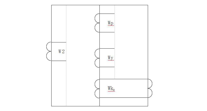
FIG. 1 Distribution of windings in the magnetometer
Wp-working wY-Balance winding I,II W2- Secondary winding Wk D-short circuit winding
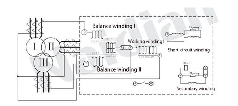
FIG. 2 Schematic diagram of internal connection
of relay and protection of three-winding power transformer
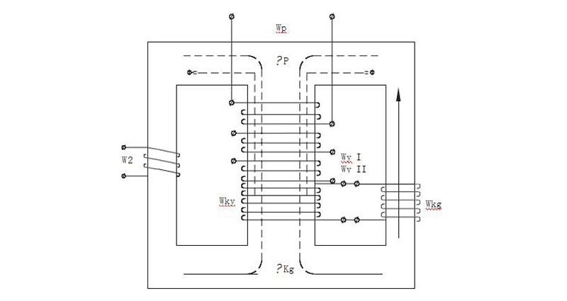
FIG. 3 Is a schematic diagram of the magnetization process within the magnetic body
Wp-working winding (differential winding) Wy I, Wy II- Balance winding I, II W' ky, W" Ky-short circuit winding
Secondary winding Φ W 2 - P - flux produced by the working winding Φ KY - flux produced by the short-circuit winding
Φ = - aperiodic component work flows through the winding current of dc magnetic flux
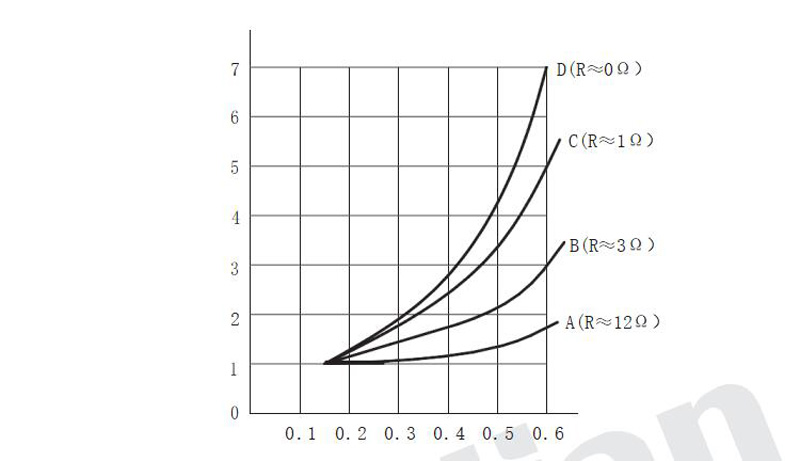 FIG. 4 Magnetic properties of a relay ∈= F (K) curve family and adjustment range (R: 012W).
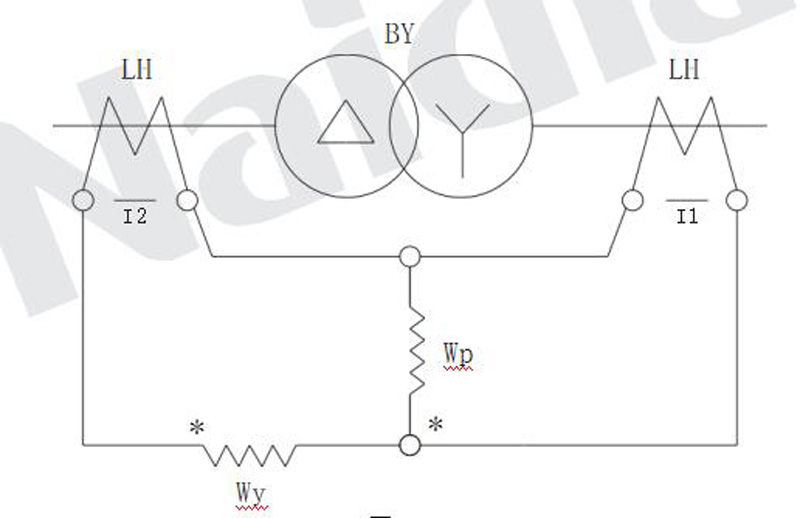
Figure 5
LH- Current transformer
BY - transformer
Wp-differential winding
Wy- Balance winding
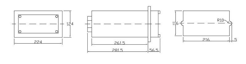
Figure 6 Outline and mounting dimensions of dCD-2A differential relay
Message feedback
News Center
Naidian Group is an electronic timer manufacturer and digital timer supplier, providing high-power relays, electronic time relays, digital timer relays, DC to AC solid state relays, and digital display timer relay knowledge popularization.
On February 26, the production of NPOWER Group resumed. The director and manager of our company personall...
NDW20 series is a compact ≤10kV relay with protection, monitoring, Modbus/CAN, and triple redundancy. Var...
A Power relay that switches 40A at 250VAC with AgCdO contacts and 1000MΩ insulation—engineered for indust...
A Power relay with 40A capacity is essential when your control panel needs to switch motors, heaters, or ...

GET A QUOTE