
Why Do Power Relay Contacts Weld Shut Under Motor Loads?
A plant engineer was building a PLC control panel to run a 15A conveyor motor. He chose a relay with 15A contacts, assuming it would last. Six months later, the relay failed—contacts welded shut. The problem was not the rating. It was the inrush current. The motor drew 60A for 50 milliseconds at start, six times the running current. The 15A relay was not designed for that surge. A 30A power relay with silver‑tin oxide contacts, rated for motor loads, would have survived.
A power relay is an electromagnetic switching device that uses a low‑power control signal (from a PLC, sensor, or timer) to switch a high‑current load. The general purpose electromagnetic relay is the workhorse of industrial control panels, offering a compact, cost‑effective way to isolate control circuits from power circuits.
This article explains why the contact rating must be derated for inductive loads, how the coil voltage (AC vs DC) changes the pick‑up time, where the contact form (SPST, SPDT, DPDT) matters for reversing motor circuits, and why the silver alloy composition (AgNi, AgSnO₂, AgCdO) determines the electrical life under arcing.
Contact rating vs inrush current: why a 15A relay fails on a 10A motor
The contact current rating printed on a power relay assumes a resistive load — a heater or incandescent lamp where the inrush current is no more than 1.5 times the steady‑state current. A motor or solenoid is an inductive load with inrush 5‑10 times the running current. A 10A motor may draw 60‑100A for the first half‑cycle. If the contact rating is not derated, the contacts weld.
The industry derating rule for inductive loads: multiply the running current by 5‑7 and select a relay with a contact rating at least that high. For a 10A motor, select a 30A relay. For a 15A compressor, select a 50A contactor, not a power relay. Power relays are typically rated 5‑30A. For loads above 30A, a contactor is the correct component.
A power relay used to switch a PLC output to a solenoid valve must also be derated if the valve has a high inrush coil. Many solenoid valves draw 2‑3A steady‑state but 10‑15A inrush. A 5A relay will work for years; a 3A relay will fail within months.
| Load Type | Inrush Multiple | Derating Factor | Typical Relay Rating Needed |
|---|---|---|---|
| Resistive (heater, lamp) | 1‑1.5x | 1x | 10A for 10A load |
| Inductive (motor, solenoid) | 5‑10x | 3‑5x | 30‑50A for 10A load |
| Capacitive (power supply, LED driver) | 20‑50x | 5‑10x | 50‑100A for 10A load |
The contact material also affects inrush withstand. Silver‑cadmium oxide (AgCdO) has the best arc‑resistance but is restricted under RoHS. Silver‑tin oxide (AgSnO₂) is the RoHS‑compliant replacement with nearly the same performance. For high‑inrush applications, specify AgSnO₂ contacts rather than fine silver.
Coil voltage: AC vs DC and why it matters for pick‑up time
A power relay coil is available in AC (24V, 110V, 220V, 380V at 50/60Hz) or DC (12V, 24V, 48V, 110V). AC coils have a shaded pole to prevent buzzing; DC coils have a simple electromagnetic circuit.
The pick‑up voltage — the minimum voltage required to close the contacts — is typically 75‑80% of the rated voltage for DC coils and 80‑85% for AC coils. The release voltage — the voltage at which the contacts open — is 10‑15% of rated for DC, 20‑30% for AC. For a 24V DC coil, the relay will pick up at about 18V and release at about 3V. For a 220V AC coil, pick‑up is about 176V, release about 44V.
AC coils have a slower pick‑up time (10‑30ms) than DC coils (5‑15ms) because the AC voltage crosses zero every half‑cycle. For a PLC output that is pulsed for 50ms, an AC relay may not have enough time to close; a DC relay will close reliably. For battery‑powered control circuits, DC coils are required. For industrial panels with existing AC control power, AC coils simplify wiring.
Coil power consumption ranges from 0.5W for small DC relays to 2‑3VA for AC relays. The holding power is lower than the pick‑up power because the armature gap is closed, reducing the magnetizing current. For a 24V DC coil, the pick‑up current may be 50mA, dropping to 30mA once closed.
Why the coil suppression diode is not optional for DC coils
When a DC coil is de‑energized, the collapsing magnetic field generates a reverse voltage spike of 100‑200V. This spike will damage PLC output transistors if not suppressed. A flyback diode (1N4007 or similar) connected across the coil terminals absorbs the spike. The diode must be connected with the cathode to the positive supply, anode to the negative side. Many power relays include a built‑in suppression diode — check the datasheet before adding an external one.
Contact forms: SPST, SPDT, DPDT — what each configuration does
The contact form determines how many circuits the relay can control and whether it can switch between two outputs.
-
SPST (Single Pole Single Throw): One normally open (NO) contact or one normally closed (NC) contact. Used for simple on/off switching of a single load — turn a heater on when the thermostat calls.
-
SPDT (Single Pole Double Throw): One common terminal that connects to either a normally open or a normally closed contact. Used to switch between two loads — for example, change a motor from forward to reverse using two contactors controlled by one relay. The transfer is break‑before‑make, meaning the NO contact opens before the NC contact closes, preventing a short circuit.
-
DPDT (Double Pole Double Throw): Two independent SPDT contacts operated by the same coil. Used to switch two separate circuits simultaneously — for example, switching both live and neutral in a 230V circuit.
A power relay with DPDT contacts can replace two SPST relays in a panel, reducing space and cost. For a 24V DC control circuit switching both the positive and return lines, a DPDT relay is required for isolation.
| Contact Form | Poles | Throws | Typical Use |
|---|---|---|---|
| 1 Form A (SPST‑NO) | 1 | 1 | Simple on/off |
| 1 Form B (SPST‑NC) | 1 | 1 | Fail‑safe (energize to open) |
| 1 Form C (SPDT) | 1 | 2 | Changeover, forward/reverse selector |
| 2 Form A (DPST‑NO) | 2 | 1 | Switch two circuits together |
| 2 Form C (DPDT) | 2 | 2 | Two independent changeovers |
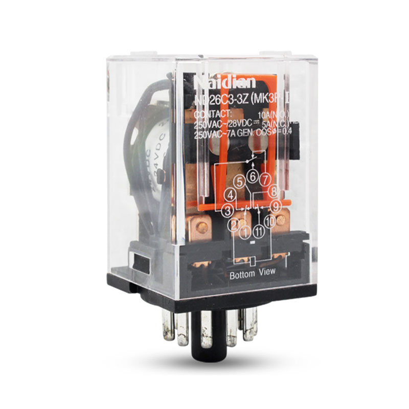
The pin configuration varies by contact form. An SPST relay may have 4 pins (2 for coil, 2 for contacts). A DPDT relay may have 8 pins (2 for coil, 6 for contacts). The pinout is printed on the relay housing or in the datasheet. Miswiring is the most common installation error; the coil pins are typically the two pins at one end of the relay, with the contacts on the other pins.
Silver alloy contact materials: AgNi, AgSnO₂, AgCdO — what changes with each
The contact material determines how many switching cycles the relay will survive. For dry circuits (low current, <100mA), silver contacts can oxidize and fail to conduct. Gold‑plated contacts or bifurcated contacts are required for signal‑level switching. For power circuits (1‑30A), the silver alloy must resist arc erosion.
-
AgNi (silver‑nickel, 10‑15% Ni): Good resistance to material transfer under DC loads. Suitable for DC control circuits up to 30A. Lower cost than AgSnO₂.
-
AgSnO₂ (silver‑tin oxide, 12‑15% SnO₂): Best arc resistance for AC loads. RoHS‑compliant. Recommended for motor loads, contactors, and high‑cycle applications.
-
AgCdO (silver‑cadmium oxide, 10‑15% CdO): Excellent arc resistance but cadmium is restricted under RoHS. Available for legacy or non‑EU applications.
For a PLC output switching a 24V DC solenoid, an AgNi contact is sufficient. For a 230V AC motor starter, AgSnO₂ is required to prevent contact welding. The datasheet will list the contact material and the rated electrical life at the specified load. A relay rated for 100,000 cycles at 10A resistive may be rated for only 20,000 cycles at 5A inductive.
The electrical life is defined as the number of operations before the contact resistance exceeds 100mΩ or the contacts fail to open/close. The mechanical life (without load) is typically 10‑20 million cycles — far higher than the electrical life under load. For a relay that cycles once per minute, 24 hours a day, 365 days a year, 100,000 cycles is about 69 days of continuous operation. For a machine that runs 8 hours per day, that is 9 months. Select a relay with electrical life at least 2‑3 times the expected number of operations over the equipment's design life.
Applications: from PLC output isolation to HVAC fan control
A power relay is the interface between low‑power control circuits and high‑power loads. Typical applications:
-
PLC output buffering: A PLC output module typically provides 0.5‑2A per output. A 10A motor or heater requires an interposing power relay. The PLC output energizes the relay coil; the relay contacts switch the motor. This also protects the PLC output from voltage spikes and short circuits.
-
HVAC control: A thermostat or building automation system sends a 24V AC signal to a power relay coil; the relay switches the 230V compressor or fan motor. The relay isolates the low‑voltage control circuit from the high‑voltage power circuit, which is a code requirement in many jurisdictions.
-
Lighting control: A timer or occupancy sensor switches a 230V lighting circuit through a power relay. For LED lighting with high inrush current (20‑50x rated), a relay with AgSnO₂ contacts and a contact rating 3‑5x the steady‑state current is required.
-
Industrial machine control: A push button or limit switch energizes a power relay; the relay switches a contactor or solenoid valve. The power relay also acts as a logic element in relay‑based control circuits, where multiple relay contacts are wired in series or parallel to implement AND/OR logic without a PLC.
-
Battery backup systems: A 12V or 24V DC relay switches the inverter input between grid power and battery power. The DC coil draws minimal current from the battery, while the contacts carry the full inverter current. A latching (bistable) relay maintains its state without coil power, preserving battery charge.
The industry standard for panel builders is to use socket‑mount relays for easy replacement. The relay plugs into a DIN rail‑mounted socket, and the socket has screw terminals for field wiring. When the relay fails, the technician pulls the old relay out and pushes a new one in — no re‑wiring, no screwdriver. A power relay with an LED indicator on the socket shows when the coil is energized, aiding in troubleshooting.
Why a pilot duty rating matters for motor loads
Some power relays are rated for "pilot duty" — switching the coil of a contactor or motor starter. The coil is an inductive load, but the current is low (under 2A). A pilot duty rating of 240VA at 240V AC means the relay can switch a 1A inductive load without derating. For direct motor switching (switching the motor itself, not the contactor coil), a horsepower rating is required. A 1HP motor at 230V draws about 8A running but 40A inrush. A relay with a 1HP rating has been tested to survive the inrush.
How the general purpose electromagnetic power relay fits into a control panel
Naidian (Zhejiang Naidian Electric Co., Ltd.) has manufactured power relays, time relays, solid‑state relays, and miniature relays for industrial automation. The general purpose electromagnetic power relay is available with coil voltages 12‑380V AC/DC, contact ratings 5‑30A, contact forms SPST, SPDT, DPDT, silver alloy contacts (AgNi/AgSnO₂), and electrical life 100,000 operations at rated load. The relay meets CE and RoHS standards and is UL‑listed for export to North America. Socket‑mount and PCB‑mount versions are available, with LED indicators on sockets for status monitoring.
A power relay that survives the inrush of a motor, isolates a PLC output from a 30A heater, and switches 230V lighting for 100,000 cycles keeps a control panel running without unexpected failures. For an automation engineer who has replaced one too many welded contacts, the general purpose electromagnetic relay with properly derated contacts, the correct contact form, and AgSnO₂ material delivers the reliability that a panel demands.
【Request a quote from Naidian】
Contact Naidian with your load type (resistive, inductive, motor), load current, and coil voltage to receive a general purpose power relay recommendation with a socket and LED indicator.
